
|
|
|
#16
 06-15-2015, 04:28 AM
|
||||
|
||||
|
Quote:

|
|
#17
06-17-2015, 07:12 PM
|
||||
|
||||
|
I just looked again at the pictures of my cabinet. The front-on
one is absolutely bizarre, I didn't notice! The left and right hand sides are not symmetric in shade. But .. they most certainly are quite symmetric in person. I've never before seen my camera do something like this.
|
|
#18
06-17-2015, 07:39 PM
|
||||
|
||||
|
That is some really nice cabinet work!
I've notice Veneer tends to reflect light unevenly, probably because of the bands of grain, that's what makes it so attractive though.
|
|
#19
06-17-2015, 08:23 PM
|
||||
|
||||
|
Finally all necessary parts have arrived. Posted is a photo of the radio chassis in its current stats. That is, rust removed, missing the motor capacitor, and the Candohm and three brodcast band coils (hopeless) detached from their moorings. All paper caps are unrestuffable,
Steve McVoy has graciously sent me defunct ones with healthy cardboard cases. Most sections of the Candohm were long ago open and bridged. Plastic insulation has crumbled. But the motor drive is fixed and works perfectly (with a suitable cap clipped in of course).
|
|
#20
06-17-2015, 08:24 PM
|
||||
|
||||
|
Quote:
|
| Audiokarma |
|
#21
06-18-2015, 06:22 PM
|
||||
|
||||
|
Your cabinet looks very nice after the restoration work. What a contrast from when you started.
__________________
Chris Quote from another forum: "(Antique TV collecting) always seemed to me to be a fringe hobby that only weirdos did."
|
|
#22
06-22-2015, 09:01 AM
|
||||
|
||||
|
I'm 40% through recapping the radio of this monster. So far only one resistor
was over 18% high and it was 1.5 Meg rather than 1.0, the 6A8 2nd grid resistor, so I left it.The area around the can electrolytic is a nightmare so I'm not restuffing it ... in any case no one will notice as their eyes will all be in the area of the former Candohm. I am restuffing the paper caps, but even with McVoy's generous stock of old ones I could not always use the original size bodies as some diameters were too small. Nor do all the ends look right ... I'm wondering: will painting the visible ends (which are hot glue) black with acrylic paint be OK? Will it flake off?
|
|
#23
06-22-2015, 11:15 AM
|
||||
|
||||
|
Acrylic should be OK. Probably too late now, but you can get hot glue sticks in many colors including dark brown similar to the original wax.
|
|
#24
06-22-2015, 12:18 PM
|
||||
|
||||
|
Quote:
__________________
John
|
|
#25
06-22-2015, 02:01 PM
|
||||
|
||||
|
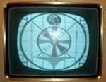
Oh, man, that cabinet is "To Die For" pretty ! What does the CRT look like ? Its one of those 3-4' long jobs, isn't it ? You're STILL a VERY lucky man...
__________________
Benevolent Despot
|
| Audiokarma |
|
#26
06-22-2015, 09:14 PM
|
||||
|
||||
|
These are not wax caps. They are either the kind with the little paper
disk at the ends with the cylinder ends rolled over it, or paper tubes sealed at the ends with some sort of black hard substance that does not melt at a temperature low enough to keep the paper the original hue. They can, however, just be pulled out. I had to remove the volume and fidelity controls to get to parts under them. I've decided to replace all parts under them with new ones because this is such a hard chose. I was able to leave lots of old rubber wires in the RF section alone because they dangle quite safely in air ... but in the audio section 100% of the non-cloth wire will have to be replaced. I got like three caps replaced today ... the rest of the time was spent in disassenbly, rewiring, and having to go back to campus to buy a new soldering iron tip since my local (5 minute walk) Radio Shack was sold out.
|
|
#27
06-22-2015, 09:44 PM
|
||||
|
||||
|
Quote:
refurbished aluminized radar tubes. I have not taken it out of its carton. I have a 12LP4 to use for testing. I too am pleased with the cabinet. Except for the side pieces of veneer on the front it was not in too bad shape overall, just scratched, needing sanding. Also, there was a large chunk out of the wood cover that fits over the CRT which needed filling in and covering over with new (and very sharply bent) veneer. They guy was able to match the original veneer closely enough that he didn't need to redo the other side. Only the bottom front and back pieces (plain wood no veneer) were badly water damaged and were replaced.
|
|
#28
06-23-2015, 10:17 PM
|
||||
|
||||
|
Little progress today. Two resistors replaced, two rotted wires,
and mostly repainting a whole lot of resistors. I painted the bodies tonight; tomorrow morning I will paint the end and ring (these are not B-E-D color code but B-E-ring). I'm using ordinary modern resistors, not worrying about size as the set had a wide variety of sizes. Doug McDonald
|
|
#29
06-25-2015, 09:47 PM
|
||||
|
||||
|
I got the radio working. 80% of resistors, all capacitors, and 40% of wires were replaced.
I first turned it on with no tubes at all inserted and nothing smelled bad, the motor tuning still worked. Then I inserted the 5U4G and found that the second-level HV was too low. It turned out to be what I worried about: I did not restuff the electrolytics, but hid replacements. One was rather close to the fidelity switch, and I was afraid to bend the switch contacts too much, so it shorted. I unsoldered the offending switch lugs and redid them, leaving 1/8 inch spacing which is fine for this voltage. This fixed that problem. Then I removed the 5U4G and inserted all the other tubes. No heaters. I had not used Deoxit on the plug that delivers power to the main chassis. Then I tried running everything inserted on a dim bulb. Nothing smelled or showed signs of a short. Setting the switch to TV or phono and touching the input showed the audio worked. Setting to radio and tuning around shortwave produced little (the broadcast band coils are defubnct, that has to wait til tomorrow.) Attaching an antenna resulted in absolutely normal shortwave reception!  chassis pictures tomorrow.
|
|
#30
06-26-2015, 08:58 PM
|
||||
|
||||
|
I got the radio finished. The bcb oscillator coil was replaced with
a Meissner "universal" one. The other atnessna and Rf amp plate coils were rewound. The set now works quite well. Pictures are, in order, a view under the fidelity switch, after reworking. Next is the finished bottom, then the front, tghen the top.
|
| Audiokarma |
 |
|
|


 Linear Mode

