
 |
|
#76
|
|||
|
|||
|
#77
|
|||
|
|||
|
One last question. The audio transformer mounted on the main board. Do I need to be worried about Silver Mica Disease? Do the caps need replaced?
|
|
#78
|
|||
|
|||
|
Anybody know how to get the cover off of the audio transformer?
|
|
#79
|
|||
|
|||
|
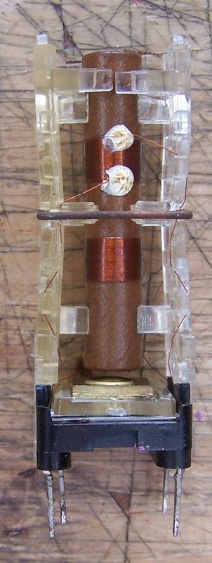
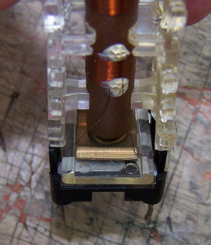
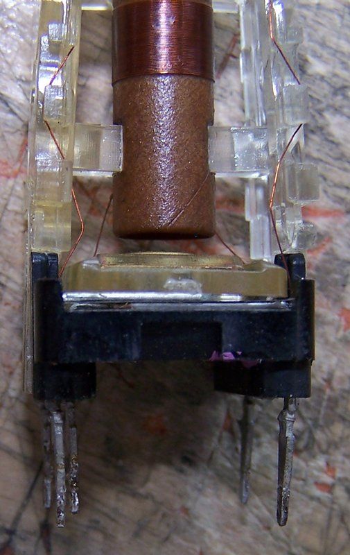
I removed the can by flattening the dimples with a smooth jawed pliers. I then pinched the can so I could withdraw the coil assembly. I wanted to inspect for any silver mica disease. None here.
Last edited by Crist Rigott; 07-04-2017 at 06:01 PM. |
|
#80
|
||||
|
||||
|
The idea of couplets always intrigues me. When I used to repair colour TV's in customers homes back in the 70's there was a Thorn model 4KA set which used a similar component called a Thick Film Unit which was essentially a couplet. It used maybe half a dozen of them and they were notoriously unreliable. You'd replace one only to have it fail a week later. Made techs look like fools unfairly. Yours will last forever I'm sure.
|
| Audiokarma |
|
#81
|
|||
|
|||
|
Quote:
|
|
#82
|
||||
|
||||
|
Great pictures of that transformer base! I repaired an identical one in a '62 Philco FM chassis. The rivet gets drilled out very carefully, then the caps can be removed. I put new caps under the PC board, not in the can.
I suggest disconnecting coils and measuring the pf value before removing it. I got lucky because an ex-Philco VK'er provided me with the values, which are not on the Sams or the Philco schematic.
__________________
"When resistors increase in value, they're worthless" -Dave G |
|
#83
|
|||
|
|||
|
Quote:
Are you saying that I should replace the caps? They looked good to me. |
|
#84
|
|||
|
|||
|
I used my 8YP4 test CRT and powered it up. After carefully checking B+ and filament string voltages, I powered it up to full voltage. I noticed that when the tubes heated up, the B+ would drop from around 270V to 140V. After some troubleshooting I found that L17 was open and not allowing B+ to get to pin 5 of V11 a 12AX4GTA Damper tube. I pulled the coil and sure enough one of the fine wires were broke off the main lead. An easy fix. Once done, B+ came up and stayed at 271V. Sams list it at 265V.
Here is what I was greeted to: 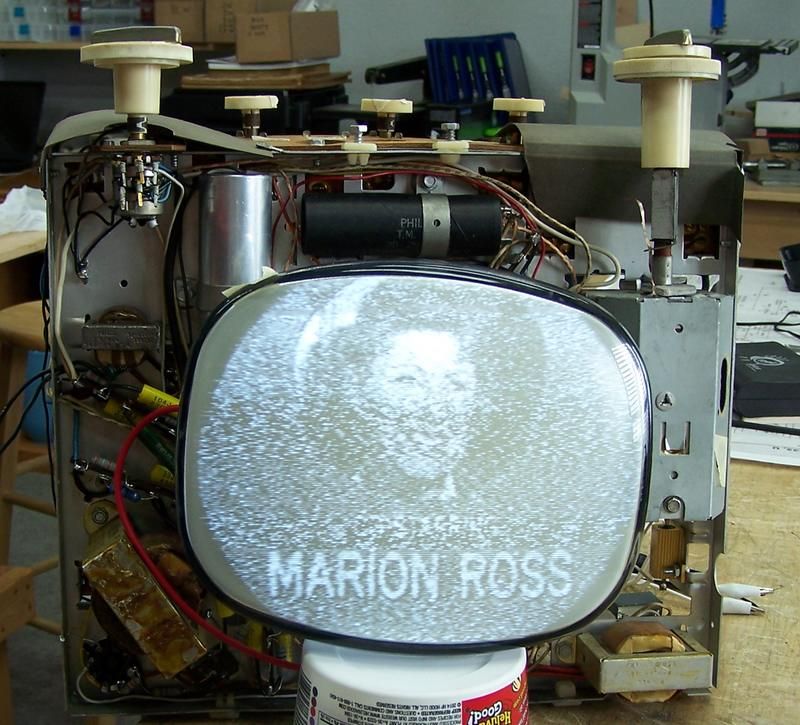 I know the picture is bad, but I also have some tubes that tested bad that I haven't replaced yet till the weekend. All the controls did something so that's good. The filament string dropping resistor R59 was a 41 ohm 20W is now a 60 ohm 25W resistor that runs very hot. My spit sizzled when applied with a craft stick. Do they always run that hot? Do I need to go with a larger wattage? I went to 60 ohms because my line voltage is 122vac. Another thing I need some help with. I have no audio. The volume pot does increase and decrease the "hash" so I know downstream of the volume pot is working. I did some troubleshooting and found L14 the 1st IF coil is open. 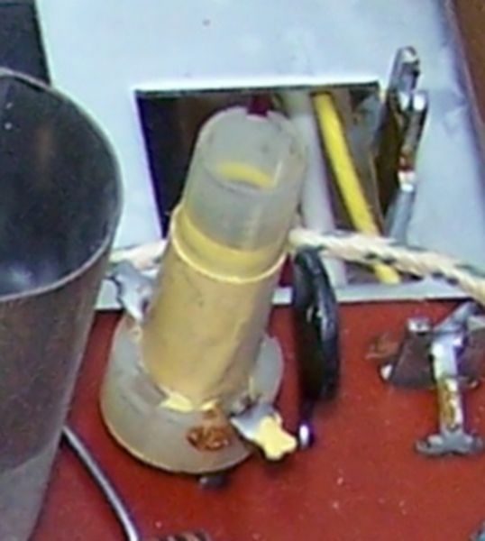 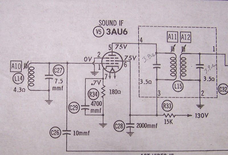 It's a simple coil and I have to pull the main board to either fix it (fingers crossed) or replace it. the Philco part number is 32-4644-12 with no other manufacturer listed as a substitute. I did try jumpering across the 2 terminals to short it out to see if that was the problem of no audio. Jumpering didn't help. I even heated up both terminals and re-flowed the solder, still no joy. I hoping that when I get some of the tubes replaced the picture and audio will be improved. As a long shot, does anybody have one of those coils? |
|
#85
|
|||
|
|||
| Audiokarma |
|
#86
|
||||
|
||||
|
Quote:
Perhaps use a diode dropper for the heaters? 122v times 0.707 equals 86.25 volts... close enough to 88? jr |
|
#87
|
|||
|
|||
|
Could you explain what that is? I'm not familiar with those.
|
|
#88
|
||||
|
||||
|
Simply replace the heater drop resistor with a diode... it will clip off half of the 122v sine wave. The resulting true rms voltage of the clipped waveform will be 0.707 times the input voltage. 1N4007 will work fine in this application.
jr |
|
#89
|
|||
|
|||
|
That simple? Lets see. My input voltage will be 122v times .707 equals 86.254 volts. The heater string is looking for 88 vac. So a single resistor will replace that big honking heater? I like it!
Thanks. |
|
#90
|
|||
|
|||
|
OK, tonight I pulled the main board and removed L14. Sure enough I found a wire broken. It came from the top of the coil down the side and to the terminal lug. It was broken in the middle. I unwound 1 coil and soldered it to the terminal. I then coated the coil with super Corona dope to secure the windings. Then I re-wrapped the coil with some yellow tape.
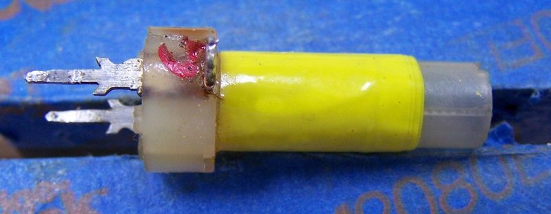 While I had the main board out, I checked all the other coils and they were good. The yellow tape had fallen off the other 2 so they got the dope and tape treatment. I then pulled L15 again because I couldn't adjust the slugs. I think they were glued in place. I used the heat gun and applied just enough heat to loosen the slugs. After it cooled off the slugs could still be adjusted. I reinstalled it and the main board. I also removed the filament dropping resistor and installed a 1N5408 diode in its place. I reassembled it and turned it on. I got a picture but still no audio. 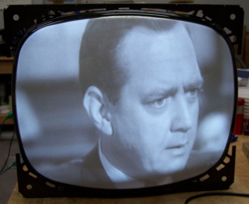 I then just started to twiddle the slugs on some of the audio coils. Viola! Real good clear audio. The picture and audio on this set is amazing. It's the best TV I've had so far! |
| Audiokarma |
 |
|
|