
|
|
|
#31
 04-19-2018, 09:13 PM
|
||||
|
||||
|
Quote:
-Steve D.
__________________
Please visit my CT-100, CTC-5, vintage color tv site: http://www.wtv-zone.com/Stevetek/ 
|
|
#32
05-02-2018, 10:03 PM
|
|||
|
|||
|
Over the last few weeks I was able to get the chroma circuits working marginally. They could be better. I found the original, from 1957, 3.58 mc crystal to be dead. I installed a newer crystal. This set uses color killer and color burst pots, which seem to have no effect on turning off the color. The color signal passes through anyway.
I extended the black plastic yoke spacers. This made it easier to draw the yoke inward or outward and install the thumb screw nuts. After I got the color working I had to get back to the issue of color purity. No matter what I did adjusting the yoke, convergence coil assembly, blue lateral magnet or purity rings ; I was unable to get a total red screen. Last weekend at the WARCI in Madison, VK member IsthmusTV, suggested I re-install the original purity magnets as a solution. It ended up that in my case the six original purity magnets got me to a far more consistent red screen. The three magnets on the left side of the screen had the greatest effect. The three right side magnet needed almost no adjustment. Thank you Clark  . The fine convergence adjustments for this set leave a lot to be desired. When my wife and I return from the Columbus Zoo and ETF Convention,I'll get back to this set again. . The fine convergence adjustments for this set leave a lot to be desired. When my wife and I return from the Columbus Zoo and ETF Convention,I'll get back to this set again.Ed
|
|
#33
05-02-2018, 10:17 PM
|
||||
|
||||
|
The asymmetry of the pure red is really odd. Did you do a thorough degaussing both from the front of the tube and the back (in case any of the mounting hardware is magnetized)?
If you do degauss it again, retract the edge magnets first, so that you don't bake in an opposite field in the tube. Regarding the dynamic convergence, I found that it is critical to get the right spacing of the neck hardware (convergence coils and purity rings) - unfortunately, you may not be able to see the location of the convergence pole pieces if the internal dag covers them, and the service info doesn't give you any measurements of the proper spacing, so then you need to experiment, making a first guess based on the illustrations in the manual.
|
|
#34
05-02-2018, 10:42 PM
|
||||
|
||||
|
I’m probably talking out my butt, but have you examined the magnets thenselves? Ive learned they can break and cause bad things to happen.
|
|
#35
05-02-2018, 10:49 PM
|
||||
|
||||
|
It looks like you're making great progress on the CTC-5.
Did you just push the magnet adjusters or turn them too? On my CTC-2B, 4 and 21AXP based moto you can push/pull the 6 front purity adjusters for coarse adjustment and twist for fine adjustment...I did not need them on my 21FBP converted sets, but the CTC-2B did, and I found twisting them to be the best way of minimizing impurities. Quote:
__________________
Tom C. Zenith: The quality stays in EVEN after the name falls off! What I want. --> http://www.videokarma.org/showpost.p...62&postcount=4
|
| Audiokarma |
|
#36
05-03-2018, 07:07 AM
|
|||
|
|||
|
Quote:
Ed
|
|
#38
05-03-2018, 11:44 AM
|
||||
|
||||
|
Quote:
__________________
Tom C. Zenith: The quality stays in EVEN after the name falls off! What I want. --> http://www.videokarma.org/showpost.p...62&postcount=4
|
|
#39
05-05-2018, 03:30 PM
|
|||
|
|||
|
Tesla Coils Ebay
Guys,
Here is an unbelievable deal on a TESLA COIL that will do the gas test as described. It's so cheap it's hard to believe they can sell it for this amount. I have tried them and they work well. I bought 3 just in case one breaks and put it in a plastic project box to use as a piece of test equipment. here is the address: https://www.ebay.com/itm/15KV-High-V...19.m1438.l2649 Hope you guys can use this, Dennis
|
|
#40
05-12-2018, 10:55 AM
|
|||
|
|||
|
I pulled this quote from an old CTC-5 thread of Dave May in 2013. The quote is from Old TV Nut.----
" If the drives required for the red and blue guns were equal to make white, then the pattern would need to be elliptical, with the B-Y gain = 2.03/1.14 = 1.78 times the R-Y gain. (These are the ratios dividing the B-Y and R-Y axes before the chroma is modulated.) However, the red phosphor in the early tubes is weaker by about the same ratio, so equal (approximately) is correct (that is, the pattern is circular). By a fluke of changing both the green and red phosphors in later tubes, the red gun requires less drive to make white; so there was a fix to reduce the red luminance drive; and at the same time, the yellower green sulfide phosphor means that the extra R-Y drive is still needed, to approximately compensate by making the difference between reddish and greenish colors greater. So, the matrix adjustment does not have to change, and can stay with a circular pattern when a new CRT (e.g., 21FBP22) is substituted. " I was wondering if anyone has a schematic or an idea of which components were altered for the reduction in the red drive? I already found the contrast/ brightness fix schematic for the 12BY7a video cathode modification. Thanks, Ed
|
| Audiokarma |
|
#41
05-17-2018, 11:09 PM
|
|||
|
|||
|
Quote:
Ed Last edited by EdKozk2; 05-17-2018 at 11:17 PM. Reason: added picture
|
|
#42
05-25-2018, 04:11 PM
|
|||
|
|||
|
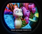
A few pictures after I adjusted the chroma board slugs to try and duplicate NTSB color bars. I found the 3.58 MHz oscillator to be out of tune, which was causing barber poling. I was able to adjust the convergence and purity a little better following the procedure in Riders' for RCA 22-149 through 22-169.
Ed
|
|
#43
05-25-2018, 04:28 PM
|
||||
|
||||
|
Looking better all the time.
|
|
#44
05-25-2018, 08:19 PM
|
||||
|
||||
|
Keep at it. Good progress.
BTW, I worked for a law firm on Court House Square “downtown” Elkhorn. My wife worked for a Judge in the Courthouse.
|
|
#45
05-26-2018, 10:47 AM
|
|||
|
|||
|
CTC-5 Super model.
I just acquired a CTC-5 super model from the HFH Restore. They're starting to sell items that seem to be so-called Antiques.
The back was hanging partially off so I looked inside to see if it's complete. I moved it closer to a power source and removed the 5U4's to see the CRT heaters light, as I couldn't see any white around the getters. Hopefully, the CRT has some life in it, as it was replaced at one time with an RCA replacement. The cabinet is a Masonite table model and a little rough. 
|
| Audiokarma |
 |
|
|


 Personal website dedicated to Vintage Television
 Linear Mode

