
|
|
|
#31
 07-06-2012, 08:01 AM
|
||||
|
||||
|
Bob,
Those multi-resistor packs would look suspicious but I'm sure you'll have a good working set after the caps are done. This may be one of the few TVs that literally build the chassis around the contour of the CRT. Nice investigative work so far! Dave 
|
|
#32
07-08-2012, 04:56 PM
|
||||
|
||||
|
All the resistors in the module were at least 20% high so I replaced them all. Not too difficult really.
The three white cylinders are capacitors and I left them alone. 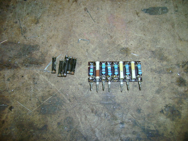 Almost done with this board. I'm waiting on a 0.0015 @ 1000volt cap to arrive. Hopefully, the two hybrid modules are OK. 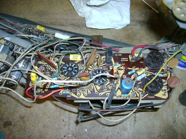
|
|
#33
07-08-2012, 06:50 PM
|
||||
|
||||
|
Looking good Bob!
You do some great work with these devices! Hell you inspired me to go find an RCA Radiola 60(probably for way too much money) and go restore it like you have been doing on you Brunswick 5KR, which has bought me a ton! I have also been doing a video series on that restoration. Cant wait to see a nice picture form that set  Matt
|
|
#34
07-09-2012, 05:10 PM
|
||||
|
||||
|
Thanks. The 5KR sure has been interesting to work on.
As for this set, I took the plunge and unwrapped all the wires from the IF board after carefully labeling them. It's a pain, but makes the board so much easier to work on. 
|
|
#35
07-09-2012, 07:13 PM
|
||||
|
||||
|
Well at least that set looks like it has decent sockets on it, on the 1956 model I'm working on the sockets are on the back side of the board and the tube pins go through the board and into the socket.
The Predictas have normal sockets so they must have learned pretty quickly.
|
| Audiokarma |
|
#36
07-09-2012, 07:50 PM
|
||||
|
||||
|
Yeah, I was pleasantly surprised to find that all the tube sockets are firmly seated with no cracked or lifted circuit board tracks.
|
|
#37
07-10-2012, 07:39 AM
|
||||
|
||||
|
Nice.
I didnt see many problems with the low-power handling tubes and these circuit traces when these little sets were popular. The sweep tubes, though... I made good money hard-wiring these sockets!! Your set looks like it hasn't had a constantly 'ON' life, unlike TV's that were in my house growing up...
|
|
#38
07-10-2012, 07:43 AM
|
|||
|
|||
|
Bob, I saw a thread some time ago where the OP had cut the wires to the boards and installed a Molex M-F connector so that the board would be easy to service again. My only concern with that would be that it may be a problem with putting all wires next to each other, which may result in coupling of signals that should not be coupled! Sounds like a lot of work. But the first time you have to remove the board again, you smile. Maybe a couple of two or three connector ones would work. But again, that may truly be overkill.
I guess you are going to just solder the wires to the wire wrap pins?
|
|
#39
07-10-2012, 12:21 PM
|
||||
|
||||
|
I investigated Molex connectors when restoring my second Predicta, and decided that the drawbacks outweighed the convenience. In this article, scroll down to "Adding Quick Disconnects to the PC Board:"
http://antiqueradio.org/PhilcoH3412L...Television.htm The boards on this TV don't have quite as many connectors, so they wouldn't get quite as cluttered as a Predicta. On the other hand, that means they are not as big a chore to remove in the first place. By coincidence, yesterday I was in a hobby store, and as I suspected, they have a variety of teeny electrical connectors for RC applications. The only ones that looked good for this purpose are very small, round male/female connectors. They were quite expensive, of course. And they offer no real advantage over using a female Molex .062 connector as mentioned in the article. When you service a board like this, I definitely recommend soldering the old wire-wrap leads back onto the pins. Phil Nelson Phil's Old Radios http://antiqueradio.org/index.html
|
|
#40
07-10-2012, 08:03 PM
|
|||
|
|||
|
Quote:
 ). A small loop around the pin, solder and it is every bit as good as when brand new. Wire wrap is often touted by the manufacturers as being better or stronger or whatever. Actually, it is quicker and time is money. I worked in the telecommunications industry and that is the reason we used wrap. The old solder frame took a long, long time but was never compromised when done correctly. ). A small loop around the pin, solder and it is every bit as good as when brand new. Wire wrap is often touted by the manufacturers as being better or stronger or whatever. Actually, it is quicker and time is money. I worked in the telecommunications industry and that is the reason we used wrap. The old solder frame took a long, long time but was never compromised when done correctly.Just my 2¢ and of course, 2¢ won't get you a cup of coffee today (or cuppa as said in Australia).
|
| Audiokarma |
|
#41
07-11-2012, 05:00 PM
|
||||
|
||||
|
I had some square Molex connectors lying around so I did a little test. They don't quite fit right over the rectangular posts, but I found that if I turn them 45 degrees it's a decent fit.
I figure I'll give them a try on a few posts. 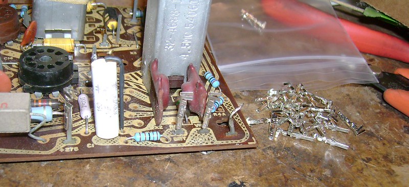
Last edited by bandersen; 07-11-2012 at 05:06 PM.
|
|
#42
07-11-2012, 11:23 PM
|
||||
|
||||
|
On the set I'm doing I just unwrapped them (They were soldered as well) when I put it back it's just a single turn around the post and a dab of solder, I figure it's a good as it ever was and not all that bad to undo the second time if you have to.
|
|
#43
07-12-2012, 09:36 AM
|
|||
|
|||
|
Quote:
|
|
#44
07-15-2012, 01:48 AM
|
||||
|
||||
|
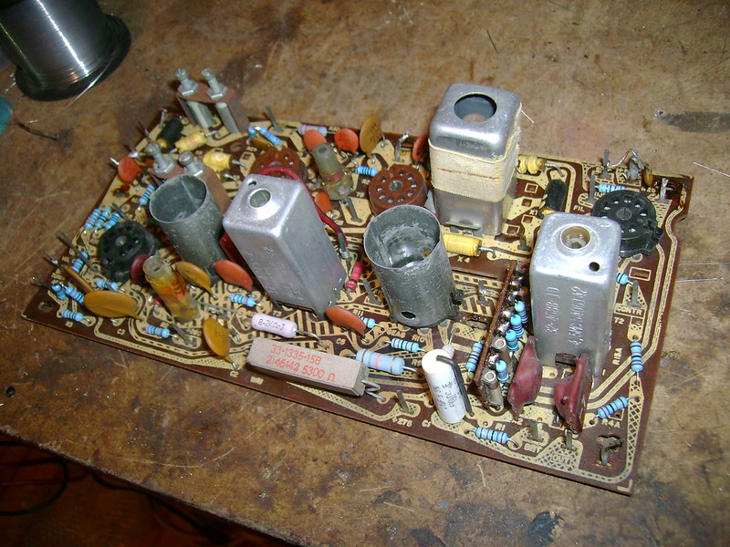
I finished with the IF board. Now, I need to remount it and check a few other components scattered around the frame. Then, I'll try firing it up again.
|
|
#45
07-15-2012, 01:52 AM
|
||||
|
||||
|
Were all the resistors off value? Looks like you replaced most of them.
__________________
"It's a mad mad mad mad world" !! http://www.youtube.com/user/mwstaton64?feature=mhee
|
| Audiokarma |
 |
|
|


 Linear Mode

