
|
|
|
|
|
#1
 02-18-2012, 10:44 PM
|
||||
|
||||
|
I'm sorry to hear about your dad and thanks for the offer. bharris kindly emailed me a pdf copy of the Operation and Application manual, but I could still use the schematics and service info. Looks like I can get them from Tucker: http://www.etestmanuals.com/Search.aspx?Mfg=SEN

|
|
#2
03-09-2012, 09:49 PM
|
||||
|
||||
|
A VK member sent me a modified EPROM that unlocks the frequency input. It's a 2716 and mine had a 2732 EPROM, but it seems to work fine
 The amplitude is a little reduced and there is some distortion on frequencies I tried, but overall it works just fine. I expect the output amplifier is designed for the 35-50 MHz range so some attenuation is to be expected outside that range. 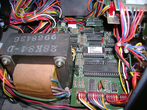  21 MHz and 66 MHz 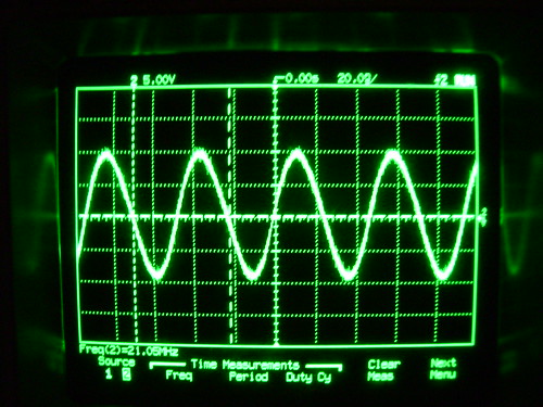 
Last edited by bandersen; 03-09-2012 at 09:54 PM.
|
|
#3
03-10-2012, 01:38 AM
|
||||
|
||||
|
Excellent!
__________________
Chris Quote from another forum: "(Antique TV collecting) always seemed to me to be a fringe hobby that only weirdos did."
|
|
#4
03-10-2012, 08:30 PM
|
||||
|
||||
|
VA62 EPROM modification
As an avid reader of these forums I came across Bob's post about wanting a wider frequency range on the VA62. A few months ago I did my first restoration on a 721TS and found out how touchy analog RF generators are to use for a marker generator. I happened to have a VA62 and its schematics which I used to fix its 1MHz reference to the PLL. Back in the day I did some digital design work. So, like Jeremy Clarkson of Top Gear (love that show) I figured "how hard could it be?". I read the EPROM, used Google to find a dissasembler, and spent a few evenings looking through the schematics and the 28 pages of assembly code. I found the code that limits the keypad frequency input to 35.00 - 50.00 MHz and changed the limits to be 3.00 - 99.00 MHz. As Bob's cool video shows, the VA62 is designed for the 35-50 range, but will work outside that range to some extent. My Run 18 VA62 can reliably be programmed for 15.00 - 99.00 MHz. Below 15 is hit or miss. My VA62 uses a 2716 2K Byte EPROM, but the schematic shows a jumper to accomodate the 2732 4K Byte EPROM that Bob's has. The 8035 microcontroller can address two 2K Byte program memory banks. It would be useful to know if there are different firmware revisions or if they all use the same version. If you want to mod your VA62 PM me. I can supply the .HEX file if you have an EPROM burner or I can burn your EPROM if you send it to me along with a prepaid box to ship it back to you. As Bob's video shows the mod requires opening the VA62, removing the old EPROM and inserting the mod EPROM. This static sensitive electronics, so you do this at your own risk.
Last edited by Zenith6S321; 09-08-2016 at 08:47 PM.
|
|
#5
03-11-2012, 06:24 AM
|
||||
|
||||
|
Quote:
  I've gotta see if Dad's VA62 is still among his stuff. He sold one that I know of (Dad had three VA62's at one point, only two of which worked). Say......you wouldn't by chance know how to modify an RCA CT100 so that it accepted a Portacolor 10VAHP22 CRT, would you???  Cheers,
__________________
Brian USN RET (Avionics / Cal) CET- Consumer Repair and Avionics ('88) "Capacitor Cosmetologist since '79" When fuses go to work, they quit!
|
| Audiokarma |
|
#6
03-11-2012, 10:47 AM
|
||||
|
||||
|
Excellent work guys!
 Everybody just go easy on the bidding wars on the VA-62's. 
|
|
#7
03-11-2012, 03:22 PM
|
||||
|
||||
|
Quote:
__________________
Chris Quote from another forum: "(Antique TV collecting) always seemed to me to be a fringe hobby that only weirdos did."
|
|
#8
03-12-2012, 07:18 PM
|
||||
|
||||
|
Thanks for the kind words. I grew up dragging home old TV sets and back then they were all tube models so I have a soft spot for them. Among them was what I now know was a Dumont RA-109 and a CTC-5. Anyway, another VK member asked if it would be possible to get video and audio modulation with a programmable frequency. I did hook up my VA62 set for 45.75 MHz to my RCA 721TS set to channel 1 and got both video and audio. There are only a dozen or so unused locations in the EPROM, so don't hold your breath.
Dave
|
|
#9
03-12-2012, 08:32 PM
|
||||
|
||||
|
It doesn't look like the signal rolls off too bad yet at 21Mhz, and probably not even worth messing with it considering the variable output level. Could they have used another PLL as a programable bandpass filter, or would it more likely be a simple high pass op-amp stage on the output?
|
|
#10
04-09-2014, 04:22 PM
|
||||
|
||||
|
VA62 rom
Quote:
and your mod is just what I need. Thanks Bob R.
|
| Audiokarma |
|
#11
04-09-2014, 06:18 PM
|
||||
|
||||
|
Yes I still have of the mod EPROMs. I will send you a PM.
Dave
|
|
#12
05-06-2015, 10:07 AM
|
|||
|
|||
|
modified eeprom still available?
Hate to resurrect an old thread, but I am interested if these modified eeproms are still available for sale?
|
|
#13
03-16-2012, 08:53 PM
|
||||
|
||||
|
I'm planning on using it as a programmable IF/RF and marker generator. Many of the sets I have require peaking each IF coil at a specific frequency then double checking the overall response cure with a sweep gen. and markers.
I'm curious about the Sencore method though. I've only read about it briefly in the manual.
|
|
#14
03-16-2012, 11:26 PM
|
||||
|
||||
|
I'm a novice at alignment, but I wanted a digital frequency marker generator for the lower IF frequencies for the older sets.
It was suggested to me that it would be useful to get an video and audio modulated IF output from the VA62 in the 15-35 MHz range. At the moment I am testing a modification that causes one modulated Cable channel number to output in that range. The +/- .25 MHz steps let you shift its frequency across +/- 9.75 MHz. I have this mod coded and it seems to work OK, but I need to make sure I did'nt break any other function. More testing is needed. Also, it looks like a physical modification will have to be made to get IF output levels as the VA62 is set to output RF levels in the cable switch positions. Suggestions would be appreciated. I was thinking of adding a switch, but I think it will need to be a triple pole double throw. Dave
|
|
#15
03-17-2012, 09:45 PM
|
||||
|
||||
|
Low band IF and level modification
Here are some pictures of what I ended up with to make the VA62 output an IF level modulated signal for the 15-35 MHz IF band and IF level. I found an error in the VA62 block diagram showing the wiring for the RF-IF Signal switch. The corrected wiring diagram made adding a manual RF/IF output level switch easy. One piicture is a dagram of the switch with the circled numbers that are the terminal number of the wires removed from the RF-IF Signal switch that are wired to the new manual DPDT RF/IF level switch. The pictures show before and after the switch addition.
My software modification to the VA62 EPROM uses the Prog Cable setting of the RF -IF Signal switch to change the frequency of channel number 42 to 25.5 MHz. Pressing the +/- keypad key then lets you enter an offset to shift the frequency by +/- 9.75 MHz in .25 MHz steps. There are some pictures of channel 42 with a +9.75 MHz and a -9.75 MHz offset with the output frequency displayed on a frequency counter. There are scope pictures that show the waveform and voltage level. I have not tried it with my 721TS, or tested it thoroughly, but everything else still seems to work properly. Same offer as before, send a PM and I will send a copy of the EPROM .HEX file for you to burn a copy of the modification. Or send me your 2716/2732 EPROM (keep your original safe) with an addressed, prepaid shipping, box and I can burn it for you. Dave Clarification: The numbers on the DPDT level switch diagram are the RF-IF Switch (gray one at the top of the 4th picture) numbered solder connection points. Remove the wires connected to the RF-IF switch solder connection points 8,9,10,14, and 17 and then connect those wires to the DPDT switch as shown in the diagram. The DPDT switch will then either supply power to the RF or the IF amplfiers depending on the position of the new DPDT RF/IF Level switch. Last edited by Zenith6S321; 09-08-2016 at 08:49 PM.
|
| Audiokarma |
 |
|
|


 Hybrid Mode
