
|
|
|
#1
 07-06-2005, 06:30 PM
|
|||
|
|||
|
what would it take to recondition this
My buddy wants to fix this up for his folks....and I told him I would help.
any ideas? I'm new to vintage radio..... 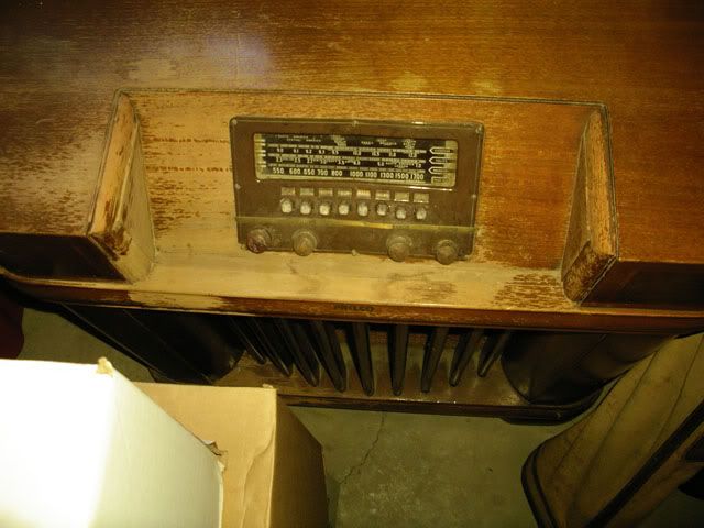 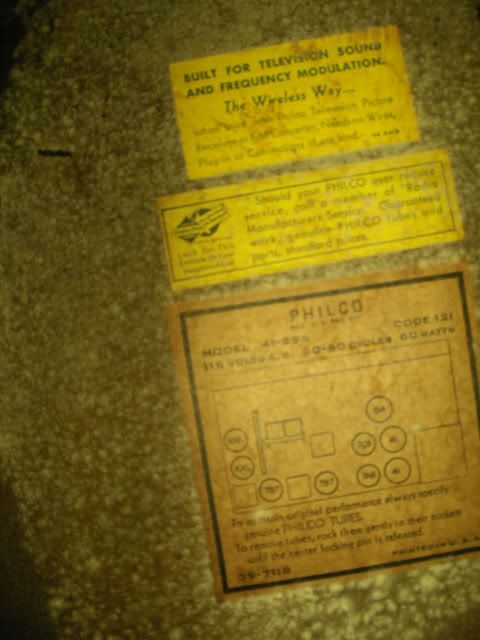 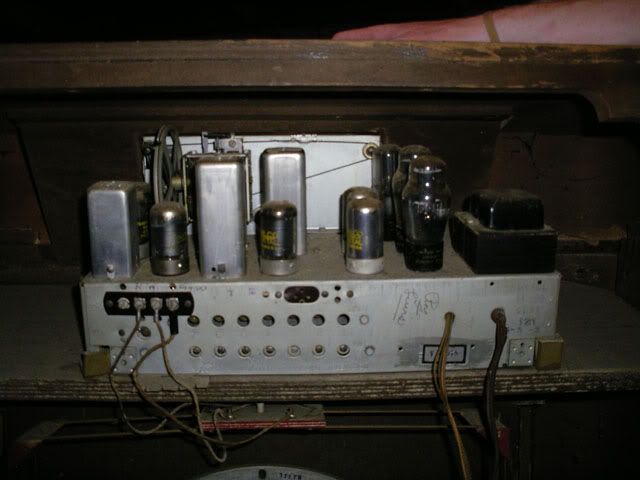 Sorry for the poor pictures....I was tremendously intoxicated at the time. BILL 
|
|
#2
07-06-2005, 07:19 PM
|
|||
|
|||
|
so, this is what I figure I can do.
Pull out the amp clean it up with damp cloth replace all the wires (as they are crumbling) replace the driver (I'll kneed suggestions for this.) power it up with a variac (I have no idea what a variac is, or where to find one) see if it works then I'll refinish the cabinet. sound good? or, am I nuts for even trying this? BILL
|
|
#3
07-06-2005, 07:33 PM
|
|||
|
|||
|
Wow - I've got a very similar set myself. I'm going to be working on that one as soon as I have found one very critical component, one that is vital for such a set and very hard to come by - a round tuit.
But seriously - it should be able to be fixed up fairly well without searching the ends of the earth. I do a lot better on the electronic side of things, cabinetwork, not so much. But it does appear that the original finish on yours is pretty well shot. I don't know if a set in this state can really be "touched up", it may actually need to be refinished. But refinishing is only a last resort, a lot of times the laquer finishes can be repaired, veneer replaced, and the set kept looking good without resorting to such drastic measures. As for the electronics, that should be easy. The tubes are all still there, as are the knobs - both items somehow escaped from my radio, likely years before I found it. But, the first thing you should do is remove the chassis. Take off the knobs (they just pull off), and remove the bolts holding the chassis down onto it's shelf. Disconnect the speaker and the whole thing should just slide out. Looking underneath and inside the chassis, there are going to be lots of old, leaky wax capacitors. These all need to be replaced. justradios.com has a great selection of caps at good prices. AES (tubesandmore.com) has them too, as well as lots of other parts. You should be able to recap the radio without a schematic, but I'd reccomend getting one. You'll want the riders for it - luckily, it looks like NostalgiaAir has it. Philco model 41-295. After recapping, power the set up with a variac or a dim bulb tester. With luck, the set will work well, most old radios normally only need a recapping and cleaning to perform quite well. Check out antiqueradio.org - they have a beginner's section on recapping and repairing radios. Definitly a good place to start. Stuff in old radios typically falls under three categories. >Must replace unless really good -Power cord. -Wax capacitors >Probably a good idea to replace -carbon film resistors greater than 1meg (they like to drift) -selenium rectifiers (modern silicon diodes are much better at not catching fire) -electrolytic capacitors >Replace only if old part is not serviceable -tubes -transformers -speaker -mica capacitors Good luck on your restoration. Read up at antiqueradio.org, build a dim-bulb tester, and let us know how you're coming along. -Ian Last edited by RetroHacker; 07-06-2005 at 07:34 PM. Reason: Typo! Sorry!
|
|
#4
07-06-2005, 08:02 PM
|
|||
|
|||
|
Excellent!
You told me exactly what I wanted to hear. Thanks so much....I hope to start playing wit hthis later this weekend! B
|
|
#5
07-06-2005, 10:29 PM
|
||||
|
||||
|
A variac is a brand name for a "variable isolation transformer". I borrowed one from a friend last weekend. It was like this one.
They allow you to bring the power up very slowly. This will sometimes "re-form" the electrolytic capacitors, and save you having to replace them (some will say replace them anyway, probably good advice). It also sometimes lets you find shorted parts without burning up any unobtainable parts. A dim-bulb tester is the cheap way. You just get a bulb socket, a plug, and an outlet. Wire this up so the bulb will be *in series* with the radio. You screw in higher wattage bulbs to raise the voltage. This way works fine. If by driver you mean speaker, youll want to salvage the old one if you can. It's probably "electrodynamic", meaning that it has an electromagnet for the speaker magnet. This electromagnet usually doubles as the choke for the power supply. The radio wont work without it. Maybe if it is bad it can be fixed. If it can't be fixed, there are other ways. You could add a choke coil. Or, you could replace the choke coil with a resistor (that was done a lot in the old days, but to really be right some other component values would have to change). What I have done in the past is mount the old speaker elsewhere in the cabinet, with the voice coil disconnected. then you can mount a regular speaker. That way the old one is still there if is becomes feasible in the future to repair it. Oh, and by the way the "41" in the model number means 1941. Have fun!  John
|
| Audiokarma |
|
#6
07-07-2005, 12:45 AM
|
|||
|
|||
|
Quote:
Please make it sound simpler than that. I'm a microbiologist! give me a pathway and I can totally follow it. "Chokes" are magnets wrapped around cables. You'ge get'n me all worried and stuff. BILL
|
|
#7
07-07-2005, 06:29 AM
|
||||
|
||||
|
That's a 1941 Philco. I've done dozens of those. If you want a quick and dirty, here it is:
1. Test all the tubes, replace the ones that are bad. 2. Replace all of the capacitors, probably a total of 8 or 10 of them, including the electrolytics. Just read the numbers off the cans and purchase equivalents. 3. Make sure the AC cord is in good shape 4. Spray the volume pot and switches up with some tuner cleaner 5. Plug it in and fire it up, enjoy the tunes that will most likely come forth 
__________________
"Restoring a tube TV is like going to war. A color one is like a land war in Asia."
|
|
#8
07-07-2005, 06:40 AM
|
|||
|
|||
|
I wouldn't be too worried, chances are the old speaker is going to be useable, they're pretty tough, and even if the paper is a little torn or cracked, it can be patched. Keep in mind that speakers of this vintage were 'paper to the edge' - no foam surround to deteriorate. You can also get speakers re-coned. It's also not hard to replace the speaker with a permanent magnet type.
Basically, in a normal permanent magnet speaker, you have the voice coil which is coupled with the cone via some sort of linkage, and you have a magnet. By sending an AC waveform into the speaker's voice coil, it becomes a magnet in itself, and becomes attracted/repelled from the big magnet, creating movement in the speaker cone which moves air and makes sound. (not a perfect description, I know, but it's easy to understand) In an electrodynamic speaker like the ones found in 40's radios and the like, the large permanent magnet is replaced by a big coil and an iron core. This magnet coil is connected to the radio's B+ supply, and when the radio is powered, it becomes a magnet. But, this magnet coil also draws current, and makes up a signifigant (well, signifigant enough) part of the load on the power supply of the radio. Without the speaker's magnet coil, or a suitable substitute load, the power supply won't be stable, or work at all. Now, this is simplified, maybe simplified too much, but I hope it wiil make sense (and that I didn't leave anything important out/give wrong info). I'm not going to get into hum-bucking coils or voice coil impedence etc. Concentrate on recapping the set, take some pictures of the underside of the chassis, the speaker, etc, and we can help you, especially with the recapping side of things. If I'm not mistaken, that set will have "Black Beauty" capacitors. They're just molded paper caps, but they're black with colored bands, and look like really big resistors. If you haven't worked with electronics much before, and/or don't have a lot of experiance soldering, read one of the many tutorials on the 'net and practice soldering bits of wire or junk components together. The great thing about working on old radios like this is that there's typically a lot of room in the chassis, and most solder connections are just a component to a terminal strip or tube socket pin. It's pretty easy to get the hang of. You don't need fancy equipment, a 30 watt Radio Shack soldering iron will do just fine. A soldering gun is handy too, for larger power supply connections and the like. There's nothing static sensitive in a tube radio. A lot of the tube sockets are phenolic or bakelite, and don't melt. Sure, too much heat can damage components, but not nearly as easily as working with modern digital logic and plastic connectors. Just be careful around the coils - the delicate tuning coils and the like, they're mounted in the squarish metal cans. You don't want to disturb them or melt them. Chances are that there is nothing wrong with them, I've never encountered an open coil. If you leave them alone they should be just fine. Keep asking questions, it's the best way to learn. And it gives people like me a chance to ramble on about electronics... We're here for you, always more than happy to help. We all learn in the process. I'm by no means an expert. I've never had any "real" training in this or anything really. What I know I've learned from reading, taking things apart, fixing radios, and talking to people. I've restored several radios and televisions, but I get stumped once and a while too. With AK, there will be someone else that can correct me or give me insight into something, and it helps everyone learn by reading the posts. Most importantly - have fun! -Ian
|
|
#9
07-08-2005, 06:53 PM
|
||||
|
||||
|
Actually, Philco liked to "pot" their capacitors in tar in bakelite boxes - but by 1941 they were using the wax coated paper ones like everyone else. They may have started using rubber insulated wire by then... it's crumbly now - the old cloth coated wire held up better.
The 4 page Philco service bulletin is on my web page: http://www.audiophool.cjb.net/Philco.html You'll need to get the DjVu plug-in from Lizardtech.com to view or print it.
|
|
#10
07-08-2005, 07:36 PM
|
|||
|
|||
|
OMG!
Thats an awsome website! thank you so much! B
|
| Audiokarma |
 |
|
|


 Linear Mode

