
|
|
|
|
|
#1
 06-10-2012, 05:32 PM
|
|||
|
|||
|
Phil what did you use on the Holiday resto? I cant see anything but the two caps and the 33k resistor, no signs of a 68k or 150k? I am assuming the same K5 is used on both models (maybe a bad assumption, dont have the sams for the holiday to compare).

|
|
#2
06-10-2012, 08:41 PM
|
||||
|
||||
|
The 9L37 chassis used in the Holiday and barberpole Predicta has a different vertical tube (10DE7 vs. 6DR7) and the value of that resistor in the vertical feedback couplate is different.
In that chassis, the couplate is named K4 (Sams) and the resistor is 150K. In the 10L43 chassis in this 17-inch Siesta, the couplate is K5 (Sams) and the resistor is 68K. The Sams and Philco manuals for chassis 10L43 agree on 68K for this resistor. Here's a snip of the Philco schematic, where the feedback couplate is named N2: 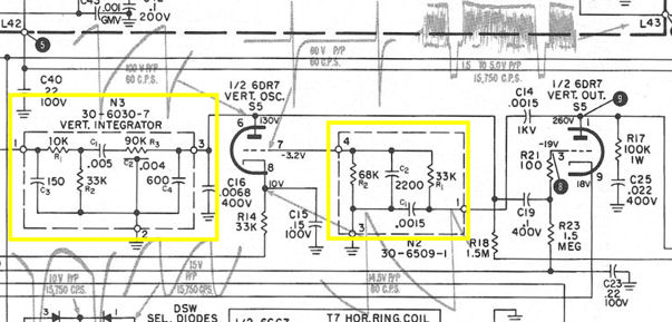 I've read competing theories on how to build the R3/C2 resistor/capacitor part of the vertical integrator couplate (N3 in this Philco schematic). One school says to put a .002-mfd cap on either side of a 90K resistor. That's what I did. Another school says to use two resistors equaling 90K and three capacitors equaling .004 mfd, one on each end and one in the middle, so the circuit looks more like your traditional vertical integrator. Both schools claim that their version works, so I wonder if the difference is really important. In all of the couplates that I've made, I put components on both sides of the perf board, so you won't see them all in a single photo. Regards, Phil Nelson
|
|
#3
05-23-2012, 09:51 PM
|
|||
|
|||
|
If there is high voltage, then there is -45 volts on the 6DQ6 grid. That goes through the 470K-560K divider to lug 21, looped to lug 40 to the 1.5 meg bias resistor and the .22 uf bias filter. If all those components are good, then the .1 coupling cap or .22 uf bias filter is leaky or the tube is very gassy.
The 100 ohm isolation resistor is not critical as long as it is somewhere in range. All this assumes there are no wiring errors. I am using the Philco service notes for things that do not show on the attached Sams print so some component designations may not match.
|
|
#4
05-24-2012, 12:37 AM
|
||||
|
||||
|
Thanks, we may be getting somewhere. I traced the negative voltage from the 6DQ6 grid, along the path you described, and it all looks reasonable until I get to the junction of the 100-ohm resistor and pin 3, so possibly something is funky there -- a bad solder joint, cracked trace, or bad socket . . . . I'll investigate tomorrow when I'm feeling fresher.
I recently got the Philco service manual, which is better than Sams in some ways. For instance, it has a wonderful diagram of the main circuit board, with a list of what all of the perimeter connecting wires are connected to -- something I had laboriously drawn by hand in the past. I scanned the Philco schematic (in two parts) in case anyone might find that helpful: http://antiqueradio.org/art/Philco10L4xSchematic1.jpg http://antiqueradio.org/art/Philco10L4xSchematic2.jpg An advantage of using the Philco docs is that the part numbers (and other IDs) match those printed on the circuit board. Regards, Phil Nelson
|
|
#5
05-25-2012, 01:36 AM
|
||||
|
||||
|
I checked the voltage divider components, 6DR7 socket, and relevant connections. All seem fine. While looking at some other voltages, the height started to bounce irregularly, and eventually I realized that the 6DR7 tube (a new one!) was failing in front of my eyes.
With a fresh 6DR7 in place, I'm getting some bias voltage on pin 3, although still weak, only about -7 volts. Currently, I have -43V on the 6DG6 grid (pin 5), -17V at the junction of divider resistors R58/R59, and -7 volts on pin 3 of the 6DR7. The picture is very nice apart from the height problem, only with a very slight bright foldover at top or bottom depending on how you adjust vertical hold, but that doesn't seem remarkable considering how compressed it is. I temporarily bridged different resistors across the 1.5-meg (R57) to see what would happen with greater bias on the 6DR7 pin 3. Even when that voltage increased to around -17V, there was no significant change in height or the operation of the height and v lin controls. I disconnected the vertical linearity pot for rechecking and it measures nearly 800 ohms max and operates smoothly. The schematic calls for a 1.5K pot (disregarding stops). I got rid of the old series resistor and installed a 750-ohm/2W resistor, making its total resistance close to 1.5K. It doesn't have a stop, but I'll just avoid turning it all the way to minimum, and meanwhile it should operate within the needed range. My 1077B Analyst does provide a vertical grid drive signal, so tomorrow I can try wa2ise's suggestion about lifting C42 and injecting the signal there. I contacted Moyers and they have the vertical output transformer in stock if I need one. Phil Nelson
|
| Audiokarma |
|
#6
05-25-2012, 12:31 PM
|
|||
|
|||
|
Phil:
With the 6DR7 removed, nothing should load the bias at pin 3 assuming you're using a high impedance meter. It could be dirt on the PC or a leaky cap. That is probably not the cause, but it should be fixed eventually. Don
|
|
#7
05-25-2012, 02:31 PM
|
||||
|
||||
|
I clipped the lead between C42 and C40 and injected the 1077B's vertical grid drive signal to C42. With the 1077B Amplitude control set about midway, the height is the same as always. Cranking up Amplitude farther distorts the picture but doesn't noticeably increase the height.
Maybe it's time to order a new vertical out transformer and see if that changes anything. Regards, Phil Nelson
|
|
#9
05-25-2012, 09:42 PM
|
||||
|
||||
|
I tried bypassing that pot with resistors of various sizes, and finally just shorting out the pot/resistor combination. Shorting it all out increased the height, but not enough to fill the screen. Bridging in an additional 100uf cap had no effect on any of those combinations.
Phil Nelson Last edited by Phil Nelson; 05-26-2012 at 01:40 AM.
|
|
#10
05-27-2012, 08:26 PM
|
||||
|
||||
|
In the interest of thoroughness, I disconnected C3C (the 100uf vert lin pot cap) and C3A (10uf, connected to height control) and checked 'em. Both are good, correct values, not wired backwards.
I left C3C disconnected and wired a fixed resistor and new 100uf electrolytic in place of the old vert lin pot/cap combination. Here's the best height I can get: 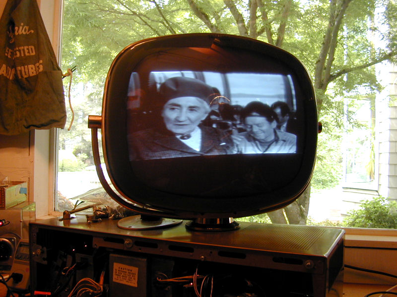 Changing the resistor's value affects the height somewhat, with smaller values giving more height. Never more than seen in the photo, however. The Height potentiometer (R7B) tests in the range of about a few K min to 2.7 megohms maximum (3 meg is specified). I tried bridging some resistors in parallel with it, just out of curiosity. I can get the height to decrease by lowering the resistance, but not increase. That pot would be an ordeal to remove for replacement or further testing. It's part of a two-pot control soldered directly to the board with eight lugs. Phil Nelson Last edited by Phil Nelson; 05-27-2012 at 08:31 PM.
|
| Audiokarma |
|
#11
05-27-2012, 10:11 PM
|
|||
|
|||
|
Fold over at the pix bottom indicates over drive. Back off until the fold over disappears, then measure the 6DR7 grid for proper wave form amplitude. If OK, then the output transformer and yoke are all that are left.
I measured the VOT primary on a working test chassis using three different meters. They all indicate 415 ohms within a few ohms. That is no guarantee yours is good. You can temporarily clip yoke lugs Y5 and Y6 together to eliminate the thermistor.
|
|
#12
05-28-2012, 01:35 AM
|
||||
|
||||
|
Here's a waveform from pin 3 of the 6DR7.
 I didn't see any vertical foldover when that was taken. The height control was fully CW, giving maximum height. A while back I measured resistance of the vertical yoke windings from the plug. Sams says each winding should measure 18 ohms and the thermistor 4 ohms cold. I measured 18 ohms between pins 10-11, and 25.2 ohms between pins 9-10 which includes the thermistor. So my thermistor measures 7.2 ohms cold, I guess. No idea what it measures when hot, but at least it doesn't look shorted or open. I see lugs Y-5 and Y-6 on the Philco schematic. I assume you pull the yoke to get access to them. Phil Nelson
|
|
#14
05-28-2012, 12:32 PM
|
||||
|
||||
|
I replaced the most recent scope pic with one that's easier to read. Refresh this page in your browser to make sure it shows up. The vertical volts/cm control is set to 5 volts/cm and the horizontal sweep time/cm control is set to 2 ms. The probe is at 1x.
I got out my HP 428B milliammeter to measure the current on the cathode (pin 9). Looks like about 38-39 ma. (The meter's set to 100 ma scale and the needle points to about .38-.39.) 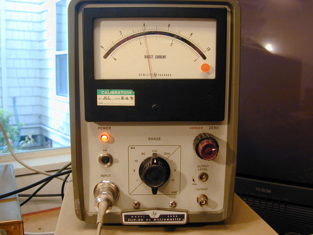 I also tried measuring the old fashioned way by bridging a .1 mfd cap on the cathode connection and putting my probes across the cap leads. With my old Triplett analog meter, the reading looked like 36-38 ma, in the same ballpark. If I interpret any of this correctly, it seems that cranking the Height control all the way up sends both the grid voltage and the cathode current too high, yet I'm still not getting full vertical deflection. While doing all this, a couple of times I heard a distinct snap from the yoke area. Maybe it's time to remove the yoke and look at that thermistor. Phil Nelson Last edited by Phil Nelson; 05-28-2012 at 12:43 PM.
|
|
#15
05-29-2012, 08:05 AM
|
|||
|
|||
|
if I read that right then the PP is only 30v on pin 3 sams shows 140v. Unless I am just reading it wrong, is the 5v for each square or each division inside each square in which case it 150v
so now you need to scope pin 6, should be 140v pp same shape. Last edited by DaveWM; 05-29-2012 at 08:45 AM.
|
| Audiokarma |
 |
|
|


 Hybrid Mode
