
|
|
 |
|
|
Thread Tools | Display Modes |
|
#1
 01-18-2016, 05:36 PM
|
||||
|
||||
|
How to repair a Mallory inductuner (Dumont RA-103, and clones) with a broken shaft
Since I can't find a thread on this anywhere, and I had to teach my self how to do this with only pictures of good tuners to go by I figure I may as well share what I've learned with anyone who may be interested.
As some of you know a few months ago I got a Dumont RA-103 Doghouse (more like a mouse house) with a broken ceramic tuner shaft, and a Stromberg Carlson TV-10 (a TV-12 with a smaller CRT) which is a RA-103 clone (it's tuner is completely missing the ceramic portion of the tuner shaft). The following advice applies to all the above and other sets that use the same tuner as the RA-103 (such as the Crosley 9-407). I restored the chassis on the TV-10 first (since as a whole it was in better shape). Since it's tuner was missing too much to be repaired I harvested the broken tuner off the Dumont and rebuilt it. It comes off by removing 3 wires on the front (I recommend removing the dial scales for better/safer access), 1 wire under the chassis, the lead to the antenna terminals, and 5 screws under chassis.  DSCN1301 by Tom Carlson, on Flickr DSCN1301 by Tom Carlson, on Flickr  The top cover was already open with the top 4 of it's 8 screws removed and it peeled back so I could see in. The shaft had broken cleanly aside from a small notch on one side, on both sides of the break. All three sliding coil contacts were off track but present, and there were several small ball bearings at the front. Even if they were missing I had/have a hopeless parts tuner on hand as a fallback/donor. I first made a partially incorrect guess as to where the bearings came from. I assumed they were from the spot where the knob portion of the shaft left the front of the tuner, which they were part of, but I did not put them in the correct spot on it (which I'll later elaborate on). After installing the bearings wrong I lubricated them and the concentirc brass rotational stops made a brace to hold the bearings in by holding the shaft forward, cleaned the shaft on both sides of the brake (not thoroughly enough) with "Goof-Off" and cleaned the contacts.   I then glued the ceramic shaft back together at the break using "Super Glue" and after that dried wrapped the surrounding shaft in 2 part epoxy to add strength, and reassembled the shaft on to it's adjustable rear pivot screw.    All seemed good until I gave the user end of the shaft the wiggle test. It had WAY too much play. I could easily un-mesh the gear on the shaft from the reduction gear for the inner rotating dial scale (which should not happen) by pushing the shaft up. Well I went and consulted the user shaft remnant on the ruined spare tuner and after coaxing a bearing or two out of it I could tell it's likely original bearing pack was different from mine. I had to spend $10 on a hex set to get the 1/20" (0.05mm) hex key to remove the front gear to be able to pull the shaft far enough out to repack the bearing properly. There are 9 balls in one from what I can tell, and it is recommended that the tuner shaft and tuner be facing down while packing the bearing. The below graphic of the removed shaft illustrates where the balls should go, and the incorrect place I initially placed them.    After repacking the bearings I proceeded to remount the shaft. I tightened the rear pivot screw down to 11 to try and reduce some residual shaft wiggle resulting in some squeaking when turning. The dial gears no longer seemed able to un-mesh so I installed the sliders and dial scales. And after some playing with the mechanism it became clear that I had not glued it perfectly straight and at some spots in the rotation the gears would un-mesh, but if I pushed down on the shaft it would keep the gears in mesh. At this point I mounted the tuner on the chassis and tested it out. It worked well for 3 sweeps through the tune-able range but on the third the tuner died....I opened it up and found the sliders had hopped out, the super glue had busted and the epoxy was BARELY holding the shaft together (allowing the sliders to pop out). At that point I waved a hammer over the tuner sub-chassis (miming out the destruction a overruled part of me wanted to dish out), and went to bed.    The next day I chipped/dissolved off the epoxy and glue with a small screw driver and "Goof Off"...Some of it came off too easy indicating I had not removed all slippery goo and dirt from the surfaces the first time. I then proceeded to re-do the process only this time with the tuner shaft totally removed, and was able to get it glued straighter (still not perfect). I did not over tighten the rear pivot this time, and since it is straighter there is no longer any problem with gear mesh, and thus I no longer have to push down on the tuner shaft (which ruined the first glue job). I also cleaned the tuner more thoroughly with "Goof Off" which got a surprising amount of dirt out of the seemingly clean coils, and also remover the stubborn dirt in the slider tracks (had to replace a slider that I broke the insulator on too). 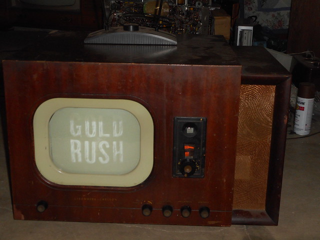 DSCN1333 by Tom Carlson, on Flickr DSCN1333 by Tom Carlson, on FlickrThis time it works and shows no signs of fault or relapse, and I can turn the shaft EASILY without putting any of the dangerous non-rotational forces that re-ruined it before. I'm now confident enough in my process that I feel I can repeat it for any tuner in similar condition to that which I got mine in. Additional processes worth explaining: Dial alignment: With the tuner shaft cranked all the way clockwise put the dark dial scale on with ch13 at the 12-o'clock position, and then put the clear dial scale on with it's ch13 aligned with the other scale's ch13 at the 12-o'clock position. Slider installation: Turn shaft and observe any vertical undulation from rotation if there is any noticeable amount (or a slider likes to pop out regularly) pinch the contact ears of the slider closer together to increase force of their spring grip. Then, while watching the coils from the top, rotate shaft to it's stop (note which direction each wire moves as it's rotated). Take a slider and press it's ears against the last turn of wire on the end of the coil the direction the wire was moving towards when turned. Once the ears are seated on the last turn keep them there and rotate the slider on the coil (or with the coil if it's easier for you) underneath til it is wedged on the beginning of the metal part that contains the slider contact track, then use a small screw driver to push it in til it seats in it's track groove. Rinse and repeat for the next two sliders. If it pops out when rotated to the other end of the coil you did not seat the slider on the right turn of coil or other things are wrong.
__________________
Tom C. Zenith: The quality stays in EVEN after the name falls off! What I want. --> http://www.videokarma.org/showpost.p...62&postcount=4 
|
|
#2
01-19-2016, 03:51 PM
|
||||
|
||||
|
Nice to see that set up and running again.
Tom Albrecht did a repair of one of these tuners. Here is his discussion on the Antique Radio Forums; I was pretty sure he did a topic here too, including pictures, but I could not find it either. http://www.antiqueradios.com/forums/...t=crosley+9407
__________________
Chris Quote from another forum: "(Antique TV collecting) always seemed to me to be a fringe hobby that only weirdos did."
|
|
#3
01-19-2016, 04:49 PM
|
||||
|
||||
|
Quote:
Seems he got lucky and was able to source a good replacement shaft (and took the easy way out). His pictures are gone and virtually no description of the details of that process were written so that thread holds little useful info to someone not familiar with working on Dumont tuners.
__________________
Tom C. Zenith: The quality stays in EVEN after the name falls off! What I want. --> http://www.videokarma.org/showpost.p...62&postcount=4
|
|
#4
01-19-2016, 08:05 PM
|
||||
|
||||
|
Your description should be quite helpful to explain these tuners and the repair process. I am glad you never got beyond holding that hammer nearby.
 Sometimes I honestly wonder if these inanimate objects do sense things, and they know when to start cooperating. Sometimes I honestly wonder if these inanimate objects do sense things, and they know when to start cooperating.One time, my boss was in town, and we were near a bank of the TV departure monitors that I support in the airport here. One of them had poor, dim video. But, as we walked up close, the bad one just snapped back in with good video, and my boss was impressed that I could fix it without even touching it. 
__________________
Chris Quote from another forum: "(Antique TV collecting) always seemed to me to be a fringe hobby that only weirdos did."
|
|
#6
01-24-2016, 08:40 PM
|
||||
|
||||
|
Quote:
It is holding up decently, with the set in somewhat regular use and periodic tuning between my agile modulators on ch7 and ch9 and the NOAA weather radio station receivable between ch7 and the FM band.
__________________
Tom C. Zenith: The quality stays in EVEN after the name falls off! What I want. --> http://www.videokarma.org/showpost.p...62&postcount=4 Last edited by Electronic M; 01-24-2016 at 08:45 PM.
|
|
#7
01-26-2016, 12:12 AM
|
||||
|
||||
|
I've now restored all the missing pictures in that thread in case anyone is interested.
http://www.antiqueradios.com/forums/...hp?f=3&t=92862 One of the disappointing things about the Antique Radio Forum is that all the pictures that were stored in its own gallery (which you would think should survive as long as the rest of the site) are now lost. I still have most of the original pics on my computer so once in a while I put them back if it looks like there is still interest in the thread. Hopefully the pictures attached now will stay for a while...
|
|
#8
01-26-2016, 05:24 PM
|
||||
|
||||
|
Question????? Is there any reason you can see which would prevent someone from using a replica shaft made from either a hard plastic or fiberglass rod?
The reason I ask, is that I also have a SC TV-10 with a broken shaft. I have the ability to machine a replica shaft in my machine shop. I feel that it would be a better route to take than trying to paste the ceramic shaft back together. But I would like your opinions about alternative materials to the original ceramic material that was used. I cant imaging why they used ceramic; it is so fragile. I realize metal is not suitable as it would most likely interfere with the electrical properties and tuning action, however there were other alternatives to ceramic when these were being manufactured. For the life of me I cant imagine why they would use such a fragile and brittle material when plastics and phenolic were available. Cant be for thermal stability. The bobbins appear to free to float laterally on the shaft. I does not appear that the tuning bobbins need to slide on the shaft laterally during the tuning action. It appears that the keyway in the ceramic shaft is evidently keyed to the hole in the tuning bobbin. Do the tuning bobbins slide laterally on the ceramic shaft???? And if I was to try and repair the original shaft, I would machine a non-metalic coupling to "splice" the shaft using JB Weld as the bonding agent. Glue alone is not strong enough to make a lasting repair. It also needs a mechanical splice to reinforce the broken area. Thanks for any input you may have RE: making a replica shaft out of a different material.
__________________
Vacuum tubes are used in Wisconsin to help heat your house. New Web Site under developement ME http://AntiqueTvGuy.com
|
|
#9
01-26-2016, 05:35 PM
|
||||
|
||||
|
Tom Carlson: If you have a precision measuring instrument, (digital caliper or micromiter) could you give me the diameter of the ceramic shaft and the width and depth of the keyway? I am going to research materials to see if I can reproduce these shafts. And at this point I am not ready to tear into my SC with the broken shaft.
Over the years I have seen a number of posts where this shaft is broken. I see a need for someone to make replicas rather than trying to fix the broken ceramics.
__________________
Vacuum tubes are used in Wisconsin to help heat your house. New Web Site under developement ME http://AntiqueTvGuy.com
|
|
#10
01-26-2016, 06:22 PM
|
||||
|
||||
|
Bob: I do not own a micrometer or calipers. I was thinking the same way you were about just replacing the shaft, but (at least on mine) the coils were attached to the shaft as firmly as if the coil forms were cast into the ceramic (they do not nor can slide along or move independently of the shaft in any way)....I felt there was no nondestructive way to get everything off the shaft so I abandoned that approach before I could do any damage.
The ceramic shaft has 2 groves 180 degrees apart running it's length.
__________________
Tom C. Zenith: The quality stays in EVEN after the name falls off! What I want. --> http://www.videokarma.org/showpost.p...62&postcount=4
|
| Audiokarma |
|
#11
01-26-2016, 09:29 PM
|
||||
|
||||
|
On a few that I have worked on, the coil forms are able to slide along the ceramic shaft. Although ceramic is brittle, it is far stiffer than most of the alternatives. The sliding contacts do put a bit of upward force on the shaft, so it needs to be stiff enough to avoid significant upward deflection. Fiber reinforced plastic might work, but I don't think any unreinforced plastic is going to do the job. I agree that they did have alternative materials (like fiber reinforced bakelite) that would have been OK.
I noticed while investigating the various designs of Inductuners used by DuMont that they did a redesign somewhere in the middle of the production run of RA-103s. One design has the shaft sticking right out the front of the set going to the user knob. These are the ones that break, since it is easy to apply pressure to the shaft in shipping. In the redesign, the shaft goes only to a gear, and the user knob shaft is a metal shaft on a mating gear. This version probably never breaks. See here: http://videokarma.org/showthread.php?t=262692&page=3 .
|
|
#12
01-27-2016, 11:58 PM
|
||||
|
||||
|
I did some research and I found solid fiberglass re-enforced fiberglass rod and also phenolic resin rod in standard sizes. I would hope that the ceramic rod would be 1/4" 5/16" 3/8" or something that would be very easy to adapt without machining the OD of the shaft. The slot/keyway is easy to machine on my milling machine using a slitter blade on an arbor.
Too bad you don't have a digital caliper Tom. You can by cheep digital calipers at Harbor Freight for about $15 to $20 depending on the model. They are not the best quality, but they are accurate. I have one and use it constantly. I guess I will need to wait till I have the time to repair my SC with the broken shaft to find out what the shaft size actually is.
__________________
Vacuum tubes are used in Wisconsin to help heat your house. New Web Site under developement ME http://AntiqueTvGuy.com
|
|
#13
01-28-2016, 09:25 AM
|
||||
|
||||
|
An alternative to JB Weld would be a high quality epoxy mixed with milled fiberglass. You can purchase bulk milled fiberglass, or you can simply take a piece of lightweight fiberglass cloth and cut your own short shavings which can be mixed with the epoxy. Combined it ends up being a white creamy color.
However, a potential long term problem with any adhesive, is getting the area clean enough to create a proper bond. And unless it's a porous material, which the adhesive can penetrate, it's about impossible to get a permanent bond.  
|
|
#14
02-20-2020, 01:59 AM
|
|||
|
|||
|
I came across this old thread, which I never read until after I repaired a broken ceramic shaft inductuner. I picked up a Crosley 9-407 at the 2018 ETF auction. The tuner was missing the three coil ceramic shaft. I just happened to have a stripped down Dumont RA-103 chassis Tom Carlson gave me in 2017. Luckily the broken coil shaft and parts were still in the tuner.
I used a solid 0.312 fiberglass rod. I cut it from a driveway reflector,that I bought at the local hardware store. Just under 6 inches is all that was needed. If anyone wants to replace a broken ceramic shaft in an inductuner , pay close attention to the direction and placement of the coils. The front two coils go one direction, and the rear RF coil is going/ wound opposite. I also had to drill a pin hole where the fiberglass shaft slides into tuner shaft. The old broken ceramic shaft had to be drilled out using a masonary bit. I assembled all the coils and shaft with the tuning control turned fully CW to the end of its' rotation. After I got everything back in place I glued the coils to the shaft. If you do use glue make sure to keep it off the metal contact rings/ washers at the end of the coils. I didn't have to make any adjustments to the tuner when I was done. The FM and TV signals came in fine. Ed Last edited by EdKozk2; 02-20-2020 at 02:05 AM.
|
|
|
|


 Linear Mode

