
|
|
|
#1
 03-17-2015, 03:32 PM
|
||||
|
||||
|
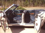
Atwater Kent Model 30 Finished...
...except for a small audio problem.
I know some of the details border on the ridiculous, but cumulatively they give a better appearance. Anyway, it looks good and it gets good reception, especially with an adequate "technical ground" (which works well, but is still experimental/developmental until I can be sure I'm not putting anyone's life at risk). The audio is fuzzy at higher frequencies, and I'll have to deal with that later. In the meantime, this is what it looks like:     This is a 16-second audio sample: https://picasaweb.google.com/coldrb/...eat=directlink For an in-depth look at the restoration (warning: 59 photos) look at this PicasaWeb folder: https://picasaweb.google.com/coldrb/...eat=directlink
__________________
Winky Dink Damn the patina, Full speed ahead! 
|
|
#3
03-21-2015, 03:52 PM
|
||||
|
||||
 Winky , gotta say you do real nice work !!! Winky , gotta say you do real nice work !!!  Now as to that "fuzziness" at high frequency , try changing out that Detector tube for a different one . It may be the photo , but that tube sure looks gassy as all Hell to me . See how most of the others have the nice bright shiny silver color ? And that Detector tube looks all milky and whitish silver ? Now as to that "fuzziness" at high frequency , try changing out that Detector tube for a different one . It may be the photo , but that tube sure looks gassy as all Hell to me . See how most of the others have the nice bright shiny silver color ? And that Detector tube looks all milky and whitish silver ?
|
|
#5
03-22-2015, 06:26 PM
|
||||
|
||||
|
Good job!
__________________
"When resistors increase in value, they're worthless" -Dave G
|
| Audiokarma |
|
#6
03-22-2015, 06:34 PM
|
||||
|
||||
|
Gassy detector? I wouldn't have known what that would look like. In person, the tube looks totally getter-silver-reflective like the others. I noticed the difference in the photo, but didn't think anything of it. It tested good on the Heathkit TT-1. I'll do some switching and see if it helps. Thanks.
__________________
Winky Dink Damn the patina, Full speed ahead! Last edited by Winky Dink; 03-22-2015 at 06:58 PM. Reason: Embarrassing technical error.
|
|
#7
03-24-2015, 07:04 AM
|
||||
|
||||
|
By all means try other tubes ! Tube testers are great for picking up major defects like open heaters and shorted elements , but are not really the final say of which tube will sound better in any given circuit . Tiny variations in things like capacitance between grids are too small to be seen on a normal emission tube tester but can and do have a profound effect on how the tube performs at higher frequencies . While this discussion of "higher frequencies" is usually had while talking frequencies like TV IF , for example , it is relevant to our old beloved triodes tryin' their best to pump out even our audio frequencies without muddying them up too badly , given the age and possible states of gassiness that could be found in almost 100 year old glass spheres with wires runnin' in and out of em . PS , your right about pictures doing funny things like making that tube look milky , I have seen this a lot with the cell phone pictures I take .
|
|
#8
03-25-2015, 12:05 AM
|
||||
|
||||
|
I have a couple of 01A's and an extra 201A. I spent some time juggling tubes, trying to find the "best" one for the detector. Didn't find any configuration that improved the sound. I did notice that at least two of the tubes I was using also have some cloudiness and I put them in the RF slots. For what it's worth, all but one of the tubes shows transconductance above or near my tester's "replacement point," but I do understand that the best tube tester is the radio itself. There are still tube configurations which I haven't tried yet, so I'll go back to that soon. Thanks
__________________
Winky Dink Damn the patina, Full speed ahead!
|
|
#9
03-26-2015, 12:53 PM
|
||||
|
||||
|
I have a Radiola 100 speaker on my AK30, its one of those high-impedance paper cone types.
I was able to improve the HF response by varying the C-voltage and grid leak resistor. Changing tubes did not seem to make much difference in mine either. What is in your Peerless speaker?
__________________
"When resistors increase in value, they're worthless" -Dave G
|
|
#10
03-26-2015, 10:26 PM
|
||||
|
||||
|
I also have a Radiola 100A which I have tried with the AK 30.
The last time I was working on the radio I had some howling as I increased the volume, so I planned to revisit the grid resistors and the grid leak. I had increased the grid leak resistor to 4 Megohms, and I will try variations on that. After that, I'll try to figure out what to do with the C-. It's now at -4.5V. Thanks
__________________
Winky Dink Damn the patina, Full speed ahead!
|
| Audiokarma |
|
#11
03-27-2015, 07:51 AM
|
|||
|
|||
|
If I recall correctly you have a 171A tube in the audio stage, if so you will need more C- on its grid and it will depend on the B+ you are using, -4.5 is not enough.
If you have a tube manual check there for the correct voltage and if not the info is online. Gregb
|
|
#12
03-27-2015, 01:39 PM
|
||||
|
||||
|
Ah, yes. I think the AK30 instructions suggest +90 B volts for the 171A. I set up the 9-pin connector so that I could switch between 90 and 135 (max) volts. The performance didn't differ between 90 and 135V, but I didn't realize that a concomitant change in C- would be needed.
__________________
Winky Dink Damn the patina, Full speed ahead!
|
|
#14
03-27-2015, 09:34 PM
|
||||
|
||||
|
I don't recall why I chose -4.5V for C-. The schematic only refers to "C-." I have data sheets for all the tubes I use, but I'm still learning how to use that data. I see -16.5V for 90V B+ and -27V C- for 135V.
...I just remembered why I used the -4.5V, but I won't go into that because I've suffered enough humility enough for one day. I'll work more on this next week when my wife goes to visit Wisconsin. Then I can play radio without being bothered by eating or bathing. I appreciate the help.
__________________
Winky Dink Damn the patina, Full speed ahead!
|
 |
|
|


 Linear Mode

