
|
|
|
|
|
#1
 02-18-2013, 12:38 PM
|
||||
|
||||
|
If I remember right, in the secondary circuit of the horizontal driver transformer, there is a resistor (1.5 ohms) and a small 15 volt electrolytic capacitor. Like the vertical chassis Zenith's, the cap drys out and the resistor burns removing a good deal of drive from the HOT. First sign of this is a foldover and a hot running HOT. Then a shorted HOT. I would always change those parts if they were original to prevent a headache. Also, but rare, a five watt resistor feeding the horizontal driver stage will open.
Looking at the flyback pictures, it looks like when the tripler was changed in the past the wre broke off the flyback and had to be resolded on. The flybacks, when failed, most the time developed a "hump" around the high voltage winding. That one looks good from the photos. How do you tell a new tripler from the pictures? Easy! No silicone seal on the connections to prevent corona on any sharp bits to act as discharge points from the wiring. And that set is HEAVY!!!! We called them 'Black Tops!" They always were upstairs which ment alot of cursing or FIX IT THERE! 
|
|
#2
02-18-2013, 11:51 PM
|
|||
|
|||
|
Quote:
|
|
#3
02-19-2013, 08:49 AM
|
||||
|
||||
|
It looks like a tripler retrofit was installed. If so, be happy. As mentioned earlier, the focus dividers (little white or yellow rectangles) mounted near the tripler would split open and hiss and then arc.
Can you hear a distinct "crackle" of the high voltage coming up when you turn the set on?
|
|
#4
02-19-2013, 05:55 PM
|
|||
|
|||
|
Quote:
Have the original focus dividers been replaced here or are they visible in any of the photos? I don't remember hearing any sounds at all when turning the set on but will check again.
|
|
#5
02-23-2013, 07:36 PM
|
|||
|
|||
|
Quote:
|
| Audiokarma |
|
#6
02-18-2013, 11:38 PM
|
|||
|
|||
|
Quote:
2) Does the NTE526 tripled replace everything next to the horizontal output transistor that is vertical (the orange board and everything attached to it as well as the second board parallel to the orange board, etc)? 3) Is the focus divider located there too? Thanks
|
|
#7
02-19-2013, 06:10 PM
|
||||
|
||||
|
The tripler is a device that contains a bunch of diodes and capacitors. It's function is to triple the voltage that comes out of the flyback transformer. The flyback outputs around 10 KV and the tripler bumps it up to around 30 KV. From what I can see, it looks like the seperate focus divider is still used.
__________________
http://www.youtube.com/user/radiotvphononut
|
|
#8
02-20-2013, 03:20 PM
|
|||
|
|||
|
Hey guys,
Does it appear to you that the tripler is not original in the photos below? One red wire in the back corner appears to have never been disturbed. I am also not sure, now, what exploded there back in the day but I do remember there was a lot of paper (like an exploded firecracker). 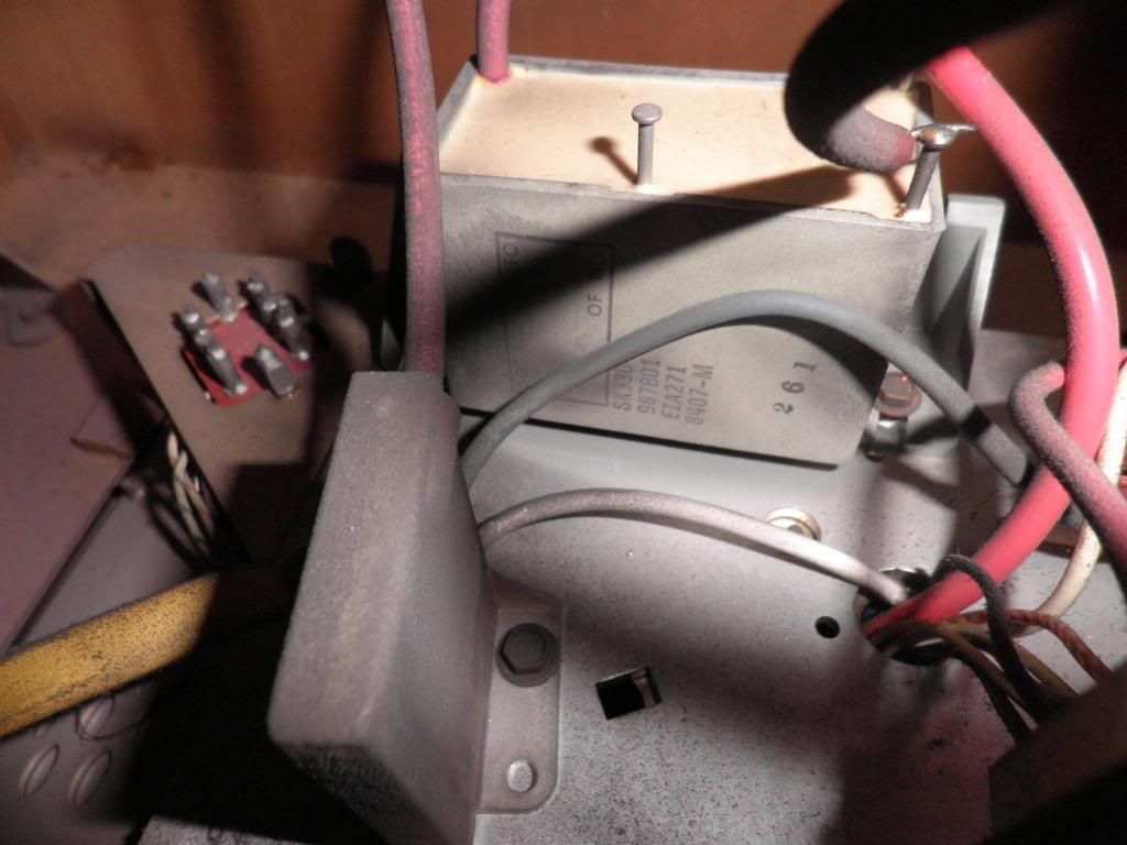 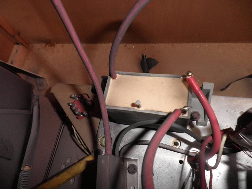 Also, could this have anything to do with the no video problem? Just noticed this ground strap from the chassis not attached under the CRT. Thanks. 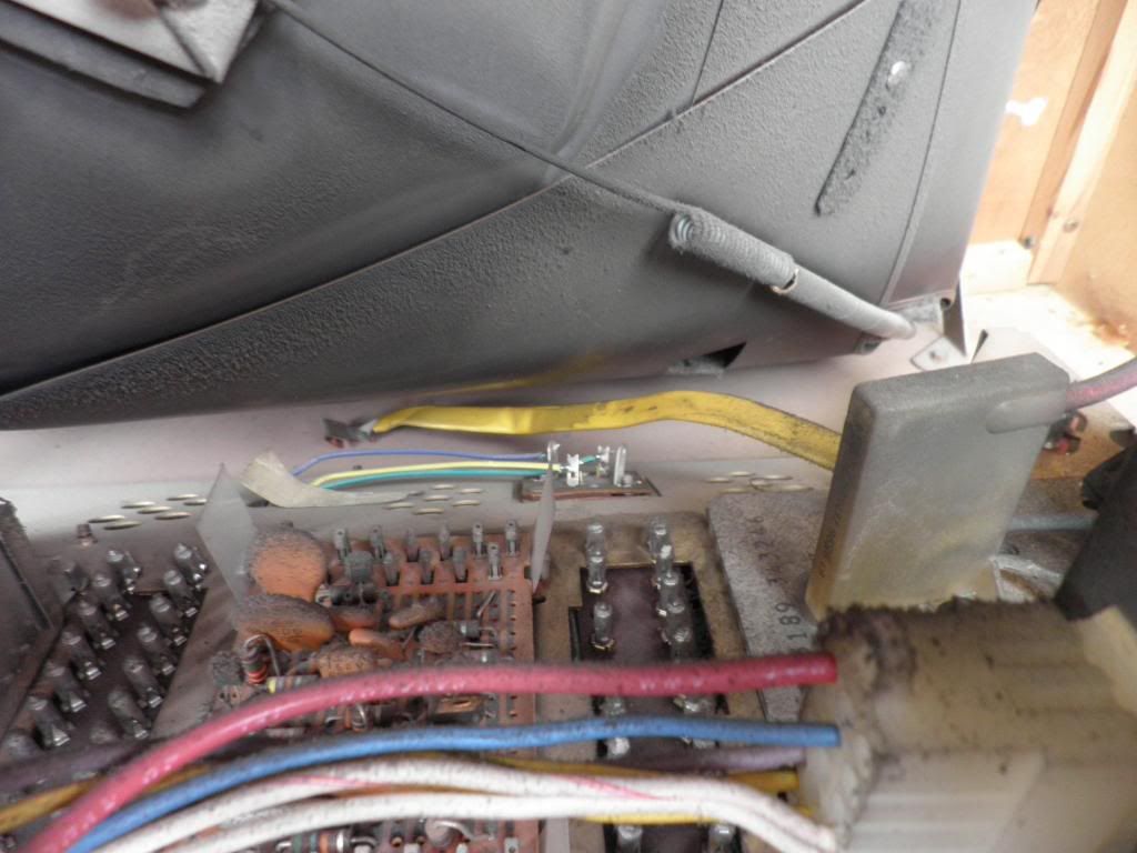
|
|
#9
02-20-2013, 05:11 PM
|
||||
|
||||
|
Quote:
The red wire in the back corner of the tripler goes to the CRT anode. It wasn't "disturbed", because it is a permanent, potted-in part of the tripler module. A new tripler included a new CRT anode lead and cap in almost every case. The 3 other terminals on the tripler should have been covered with silicone rubber sealant when the tripler was installed, to prevent corona/arcing. The original focus divider is still in place. It is the other plastic block looking component with 3 leads to the lower left of the tripler in your photo. The unused "F" terminal on your tripler is a focus voltage output, which indicates that the tripler incorporates an internal focus divider,, which isn't being used in your installation. Last edited by N2IXK; 02-20-2013 at 05:30 PM.
|
|
#10
02-20-2013, 08:07 PM
|
||||
|
||||
|
A capacitor is most likely what exploded and those white ceramic tubular caps were known to explode. When that happens, it can shoot pieces of foil and wax paper all over the place.
__________________
http://www.youtube.com/user/radiotvphononut
|
| Audiokarma |
|
#11
02-20-2013, 11:45 PM
|
|||
|
|||
|
Quote:
Also, any thoughts on the loose ground strap as a possible solution to the video problem? Haven't had a chance to reattach and not sure where to reattach exactly. Will try to pinpoint where it could've detached from. If anyone has any idea, please let me know. Thank you.
|
|
#12
02-21-2013, 08:29 AM
|
||||
|
||||
|
Those ground straps usually have a slip clip to go on the picture tube magnetic shield. I've also seen them ripped off of the CRT socket when someone was too lazy to replace a carbon trailed (arced over) crt socket.
Most likely the chassis was pulled and put on a jig for repair and the tech didn't see the ground when he reinstalled it.
|
|
#13
02-26-2013, 05:21 PM
|
||||
|
||||
|
That buzzing sound could be coming from the windings on the deflection yoke that are responsible for vertical deflection.
__________________
http://www.youtube.com/user/radiotvphononut
|
|
#14
04-26-2016, 08:59 AM
|
||||
|
||||
|
Sorry to dig up such an old thread, but I'm supposed to be getting a set just like this soon, and in my research, I found this thread. Just wanted to know if this set was ever repaired and what the problem was.
__________________
"If you wish to make an apple pie from scratch, you must first invent the universe." -Carl Sagan
|
|
#15
11-05-2019, 11:31 PM
|
|||
|
|||
|
Hey guys,
Resurrecting my old thread for some sad news. I was never able to get around to repairing the old Zenith and life has gotten very complicated. We moved my mom in with us and are selling her house. Have no where to put the set and I don't want to just kick it to the curb so wanted to let the forum know that we would like to give it to someone who would want to restore it and possibly give it a new life. It's been really hard as we did want to try to fix it but the time was just never there. So if anyone is interested please pm me as soon as possible. Unfortunately, I think it would have to be pickup only as I think the cost and difficulty to try to ship this piece of furniture would be astronomical. I think I would need to post this in the classified section of the forum (as soon as I can figure out how and where) so that more members can see it. So anyone reading this let me know. And thanks for all those who helped in this thread over the years.
|
| Audiokarma |
 |
|
|


 Hybrid Mode
