
|
|
|
#76
 07-08-2011, 07:26 PM
|
||||
|
||||
|
Thanks, $5 or $10 sounds more like it. I have loads of old wirewound resistors and was planning to put in something like 100 ohms to proceed in the meantime.
Here is the entire schematic: http://antiqueradio.org/art/Capehart661-PSchematic.jpg The 6L6 serves as both oscillator and output, I guess. Everything in the dotted rectangle at far left in the schematic is in the "horizontal AFC" subchassis that mounts above the main chassis. I thought the main chassis was cramped until I opened that thing up. Twelve (12!) paper caps in a can about the size of three Altoids tins. The manual specifies a metal 6L6, but all I have is a glass one. Haven't had time to look it up and decide whether that matters. I imagine they wouldn't have mentioned that without some reason . . . . It's an interesting set, although the layout seems a bit haphazard, with lazy-man's leads trailing all over the place. I suppose I couldn't have done any better, but those guys were engineers, for cryin' out loud, not English majors like me  Phil Nelson 
|
|
#77
07-08-2011, 08:39 PM
|
||||
|
||||
|
That sure is a strange and interesting design. If it does matter, I have some spare metal 6L6s.
|
|
#78
07-20-2011, 01:51 AM
|
||||
|
||||
|
Hey, would it be safe to pull the 6L6 oscillator/output tube and power up the set long enough for some quick voltage checks?
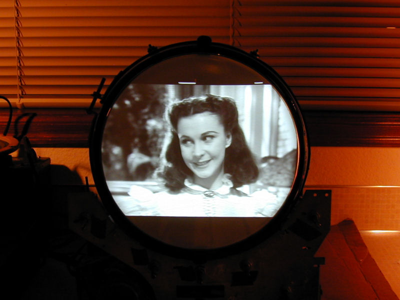
(And while we're answering questions, can someone explain how this circuit works?) After recapping and replacing loads of bad resistors and the toasted width control, I got a raster of sorts (below) and so-so audio. Also very weak HV (~3KV) and a faint sizzle sound from the HV section, so I quickly powered down. The set was drawing 360 watts, more than the specified ~300. Given this, and the amount of burned-up stuff I've found, I suspect there is lots more fun in store. I'm grinding through the resistance chart, but I'd also like to check some voltages if that can be done without risking the flyback, since I usually learn more from voltage readings. Phil Nelson 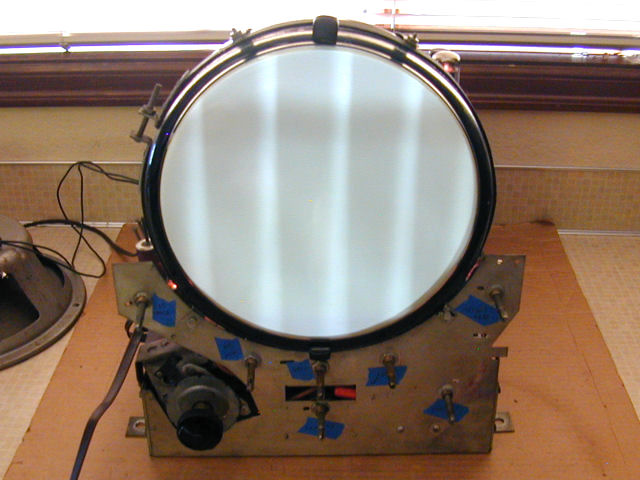
|
|
#79
07-20-2011, 09:48 AM
|
|||
|
|||
|
Phil,
What heater voltage are you getting? Is it smack-on 6.3V? With the 6L6 removed, does the AC line draw drop at all? Then if you remove the 5U4s one at a time, does it drop signifigantly? Basically, the idea is to remove as much load as possible from the power tranny so as to rule out the possibility of it having a shorted turn somewhere. Same idea as the 'dim bulb' test in old radios with all tubes removed. oc
|
|
#80
07-20-2011, 02:58 PM
|
||||
|
||||
|
The heater voltage (H1) from the "Television" power tranny is high, as is the current draw. When I pull the 6L6, and then the two LV rectifiers, the watts go down and the heater voltage goes up. Same when I pull all tubes, only more so.
The line voltage here is 120.2 VAC. I'm not using my metered variac to reduce line voltage because its needle pegs out at 300 watts. With all tubes pulled, heater voltage (H) coming from the second ("Radio") power transformer is 6.8 VAC. Phil Nelson 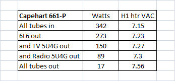
|
| Audiokarma |
|
#81
07-20-2011, 04:32 PM
|
||||
|
||||
|
The metal 6l6 is used in RF shielded applications. I have subbed glass ones without problems (so far) in some transmitters. I doubt the RF on that tube would affect anything but if the picture gets weird lines in it that would probably be the cause.
|
|
#82
07-20-2011, 08:12 PM
|
|||
|
|||
|
Phil,
At 17 watts with all tubes out, It looks like the power trannys are OK. Why doncha try this.. hang an AC voltmeter on the TV heater supply, and with all tubes in, bring the set up on your metered variac till it's reading 300 watts. Is the heater voltage somewhere near 6.3V now? And what's the AC voltage going in? I'm betting it's somewhere around 105-110 volts. If such is the case, you probably could use a bucker on the TV power tranny's primary to bring the line voltage down. Or a power resistor of maybe 5 ohms @ 50W if you have anything that big. A grounded metal can temporarily over the 6L6 might reveal whether those 'drive lines' are related to shielding or not. Man, i'm fascinated by that circuit. First one i've seen the schematic of. oc Last edited by old_coot88; 07-20-2011 at 08:15 PM.
|
|
#83
07-21-2011, 12:33 AM
|
||||
|
||||
|
Bill you should start charging for these predictions
With all tubes back in and using the variac, I get 6.3 VAC heater voltage by setting the line voltage at 110 VAC, just as you said. As long as I had all the tubes out, I decided to re-test all of them, just out of superstition. All had tested good initially, but now I found three bad ones -- one of the HV rectifiers, one in the tuner, and one of the video amps. I guess they were just on their last legs. The horizontal frequency was far off, but the picture popped into place after only a few rough adjustments. 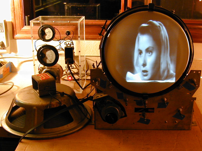 The photo was taken before I turned the line voltage down. At 110 VAC, the set draws a comfortable 285 watts and the picture's bright and well focused. Although this project's far from done -- note the wicked vertical foldover at the bottom, for instance -- I think there's hope for this little mutt after all, and my salvaged CRT looks plenty strong. A humbucking transformer sounds like just the ticket for this set. I have read about them before, but never tried making one. Thx for the good advice, as usual. Phil Nelson P.S. The "Television" power transformer appears to have some kind of taps -- presumably for different line voltages -- and a rotary switch on the top, but I can't get the darned switch to move at all, and it's installed with rivets, so I'm inclined to let that sleeping dog lie. Last edited by Phil Nelson; 07-21-2011 at 01:23 AM.
|
|
#84
07-21-2011, 10:57 AM
|
|||
|
|||
|
Yo Phil. Hey no payment needed. The 'pay' is in the pleasure of vicariously 'working on' the old beasties and helping bring them back to life, and hopefully passing on some useful info and tips along the way.
 Regarding a bucker, you could probably use something like a 12V filament xfmr rated for 3 amps or better. Or an old radio power xfmr with the 6.3 and 5 volt windings in series (and in phase). Just put the bucker winding in series and out of phase with the TV's primary. oc
|
|
#85
07-21-2011, 05:51 PM
|
||||
|
||||
|
Quote:
If I remember right it isn't a "switch". Without pulling my set out, I think you pull up on the knob till the pins are clear of the socket then turn it for the correct input voltage and push it back in. Chuck
__________________
www.myvintagetv.com Learn from the mistakes of others - You can't live long enough to make them all yourself.
|
| Audiokarma |
|
#86
07-21-2011, 05:59 PM
|
|||
|
|||
|
Yeah, it'd be great if the selector thingy could be utilized without having to do the bucker or dropper routine.
oc
|
|
#87
07-21-2011, 06:40 PM
|
||||
|
||||
|
Quote:
__________________

|
|
#88
07-21-2011, 07:16 PM
|
||||
|
||||
|
Looking good Phil
 What a PITA about those tubes deciding to faulty after testing ok... Don't ya hate that! There's one thing about old components being faulty but when something new or tested ok decides to fall over it can really lead to some head scratching.... All part of the hobby though.... What a PITA about those tubes deciding to faulty after testing ok... Don't ya hate that! There's one thing about old components being faulty but when something new or tested ok decides to fall over it can really lead to some head scratching.... All part of the hobby though....
__________________
Visit my Vintage TV & Radio Page - http://nzvintagetvradio.blogspot.com/ My YouTube Link - http://www.youtube.com/user/glenz1975?feature=mhsn
|
|
#89
07-21-2011, 08:53 PM
|
||||
|
||||
|
Quote:
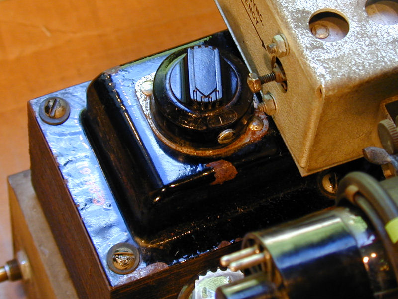 It has a setscrew and what looks like four positions. If I remove the setscrew, it feels like a rotary switch that's stuck. Turning the narrow top portion nudges it slightly inside its metal case, but not enough to click to another position. Pulling up with fingers gets you nowhere, although I guess it could also be stuck that way. The flat portion appears to have four settings, and you can see four (or is it five?) taps on that transformer: 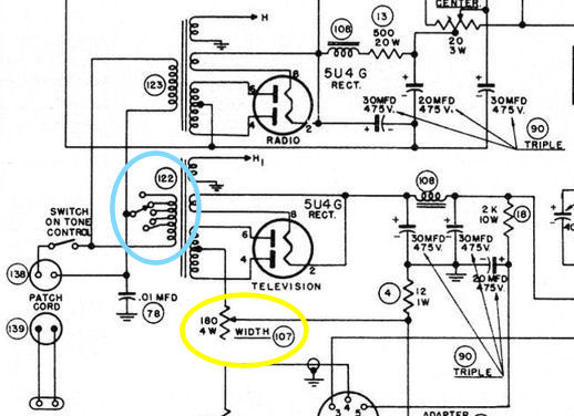 The manual says "Supply source...105-120V," but doesn't explain how to work this gizmo. If it's on a lower setting, I suppose that would account for excessive voltages with a line voltage of 120V. I'm not terribly surprised that a couple of tubes failed. The set had been completely de-tubed, and I had to scrounge pretty hard to find all 28 tubes that were needed, digging through old boxes and borrowing a few from other sets in the house. I just remembered that I have an old TV Isotap somewhere in the rubble. If I can't get the voltage selector to select anything different, I suppose I could just use that. Phil Nelson Last edited by Phil Nelson; 07-22-2011 at 02:38 AM.
|
|
#90
07-22-2011, 12:40 AM
|
||||
|
||||
|
Quote:
 The audio improved dramatically after a little tweak of the sound IFs. Need to work on HV output and everything else remaining on the list, of course. This seems like kind of a low-buck set, overall -- nobody would mistake it for a DuMont! -- but it's shaping up OK and I like things that are different. Phil Nelson
|
| Audiokarma |
 |
|
|


 Linear Mode

