
|
|
|
#106
 02-15-2012, 05:46 PM
|
||||
|
||||
|
I'd like to tell a cautionary tale for any one reading this that wants to learn from other peoples mistakes, rather than make their own.
Rebuilding multi-stage electrolytic capacitors has been the most challenging thing I've done thus far on this restoration. As those of you know who have been following this thread from the beginning, I replaced all of the paper and electrolytic capacitors in this set before I applied power. Due to a misprint in the schematic I put a 160v capacitor where a 450v capacitor belonged. What I was greeted with was a cloud of capacitor smoke. Taking the schematic at it's word and thinking that I some how miswired the restuffed capacitor I rebuilt and hooked up the same valued capacitors outside of the set to have visual confirmation that my leads were ok. Again I was greeted with a pop and a cloud of foul smelling smoke. Slightly frustrated at this point I dived into the schematic, and the wiring of the set and deduced that the voltage rating of the cap was indeed the problem. At this point I had two things going against me, I was frustrated because I had two "failures" and I was cocky because I, a rookie, had "cracked the code" and figured out that the schematic was incorrect. I should have turned the lights out and came back another day, I didn't. What I did was hurry to rebuild the capacitors in question so that I could feel like progress was being made and I could shoot that nice raster picture to post here. The result was an incorrectly wired capacitor that was done in such a way that even when another cap was jumped across it's leads it wouldn't show itself. I can, however, take a positive away from this mistake, and that is what I have learned through the trouble shooting steps that the knowledgeable and helpful people here at VK led me through. Learn from my mistake, when frustration or any other emotion that forces you to work anything less than 100% focused and deliberate, turn the lights out and come back another day. Now for the good news. The set currently resembles a patient on life support as I have frankenwired some capacitors outside of the set to take the place of the multi-stage can in question. 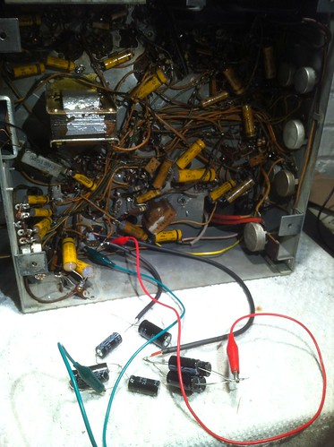 I have ordered smaller replacement capacitors for that section but for now I have a much better picture on screen  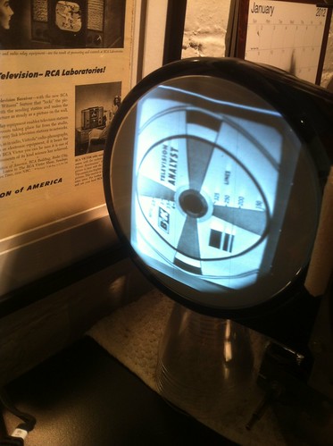 There is still much work to do, but for tonight I'll turn the lights out and come back another day. 
|
|
#107
02-15-2012, 07:17 PM
|
||||
|
||||
|
Quote:
 Not tooting my own horn or anything, but I had a feeling that was the problem. Can't blame yourself though, I frequently find errors in schematics so it's not a very big leap to assume something was misprinted. Glad you found out what was causing the issue, pic looks great from what I can see. 
__________________
Evolution... 
|
|
#108
02-15-2012, 08:09 PM
|
|||
|
|||
|
And, also at the risk of sounding "cocky", if you are replacing a multi-section capacitor, the values are usually written on the can so you can "double check" the schematic. Bet the error was in a Sams Photofact? They are usually good but can have mistakes. Glad you sorted it out...
|
|
#109
02-15-2012, 08:15 PM
|
||||
|
||||
|
Congrats, I'm glad you got it sorted out too
|
|
#110
02-16-2012, 09:16 AM
|
|||
|
|||
|
Good job of sleuthing it out, Mr. Dragonslayer.
 And you learned an important point too: Sams is notorious for misprints and diagram errors. The old adage "Trust but verify" always applies. I liken it to riding a bike on city streets. Assume every parked car door is going to swing out on you. And you learned an important point too: Sams is notorious for misprints and diagram errors. The old adage "Trust but verify" always applies. I liken it to riding a bike on city streets. Assume every parked car door is going to swing out on you.BTW, which cap was it?
|
| Audiokarma |
|
#111
02-16-2012, 11:11 AM
|
||||
|
||||
|
Quote:
 turn the lights off and return when you're turn the lights off and return when you're  . .
|
|
#112
02-16-2012, 12:52 PM
|
|||
|
|||
|
I need to learn to re-read stuff. Doh.

|
|
#113
02-19-2012, 02:21 PM
|
||||
|
||||
|
Making some more progress on the set. I went though every resistor in the horizontal circuit and replaced quite a few that were way out of spec, or completely open. I fired the set up after each replacement to make sure nothing went wrong, and to enjoy seeing the picture get better and better with each step. I still have (at least) two problems with the video currently. One problem I could not get completely sorted out with resistor replacement in the horizontal circuit was a bit of tearing at the top of the screen.
 It was easiest to photograph the phenomenon by injecting video right at the grid of the video amp and adjusting contrast until it showed up. It is possible to get a stable picture most of the time, but when there is full motion video on screen it will occasionally tear horizontally at the top of the screen, just like the picture above but some times much worse. The last set I worked on had a Sams for it and gave a procedure for horizontal adjustment. I cannot seem to find one in the Rider for this set however. Maybe it's just a matter of adjustment that I'm missing? My other problem is before the video amp. I'm getting some trailing ghosting in the picture. 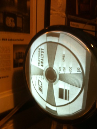 I haven't dived into this problem just as I would like to get the horizontal sorted first but thought I'd share.
|
|
#114
02-19-2012, 03:17 PM
|
|||
|
|||
|
In regards to those trailing ghosties, be sure and check peaking coils L105 and L106 for continuity.
Seems like the tearing/'flagging' is related more to signal overload than horiz. adjustment since it straightens up as you lower the contrast. This set doesn't appear to have any AGC (automatic gain control) at all. The contrast ('Picture') control adjusts the gain of the 2nd IF tube, requiring you to manually adjust it for varying signal strengths. Too strong a signal and the pic gets the bends. Just one of the charms of the old beasties, sorta like riding the gain on an old TRF radio. Last edited by old_coot88; 02-19-2012 at 04:21 PM.
|
|
#115
02-19-2012, 05:35 PM
|
||||
|
||||
|
Quote:
I've shot a couple of videos of what the set is doing. The first one is from the B&K 1077 and shows that the two problems seem to be interrelated. When I adjust the picture control I can get a steady picture with ghosting, or a ghost free picture with tearing, but not both. The ghosting is much easier to see in the black blocks at the bottom of the screen (is there a proper name for those blocks?). http://www.youtube.com/watch?v=rLJRdzFB-yU The other video displays the occasional horizontal tearing towards the top of the screen with full video that I described before. http://www.youtube.com/watch?v=28X9hkIWCQE I'll check the resistors and voltages in the video and if stages next to see if anything jumps out there.
|
| Audiokarma |
|
#116
02-19-2012, 05:44 PM
|
||||
|
||||
|
The tearing seems to be from overloading, the ghosting possibly some misalignment in the i.f.'s?
|
|
#117
02-19-2012, 07:57 PM
|
||||
|
||||
|
Whaddabout the case ? I have a VERY GOOD furniture refinisher here...I've used them quite a lot & they understand about tube diagrams, decals, etc.. Just sayin. PM me for their addy/phone #
__________________
Benevolent Despot
|
|
#118
02-19-2012, 08:03 PM
|
|||
|
|||
|
The 'ghosting' doesn't look like the smearing/ringing of fine detail you typically see with IF misalignment.
What happens if you inject video at the CRT grid, working back point by point? Have to reduce the B&K's output as you move back (to keep the pic from flagging) and reverse the phase a time or two. See at what point the ghosting appears.
|
|
#119
02-19-2012, 09:01 PM
|
||||
|
||||
|
Quote:
all the more time to perfect the chassis.
|
 |
|
|


 look your wife will give you when you smell up the house.
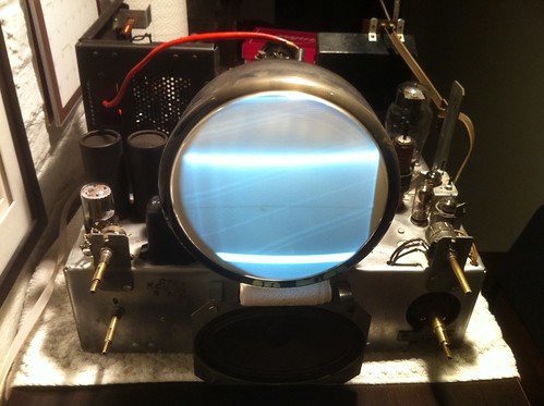


 Linear Mode

