
|
|
|
#121
 02-20-2012, 06:35 PM
|
||||
|
||||
|
Much to report to all of you. First off I replaced my temporary modern Radio Shack resistors with some beautiful old carbon resistors. "Out With The New, In With The Old!" That's all kind of boring and just those things you do when you want an original look at the end of the restoration. On another note I have finally got off my
 and got an oscilloscope for the bench. I put the scope into service right off the bat testing a theory. If you remember I had two problems, ghosting in the image and some horizontal tearing towards the top of the screen. I had previously noticed that the two were mutually exclusive as I adjusted the picture control. After thinking about it overnight I thought that maybe the ghosting problem was me over-driving of the signal (as old_coot88 explained before " The contrast ('Picture') control adjusts the gain of the 2nd IF tube"). I used the RF Attenuation control on my B&K to achieve the same results as adjusting the picture control on the set. What I got was horizontal tearing at the low end of the signal and as the gain was cranked up the tearing disappeared but the ghosting appeared. What I theorized was that the horizontal sync pulses were being attenuated at a normal signal level forcing me to overdrive the signal to bring it back thereby inducing ghosting. and got an oscilloscope for the bench. I put the scope into service right off the bat testing a theory. If you remember I had two problems, ghosting in the image and some horizontal tearing towards the top of the screen. I had previously noticed that the two were mutually exclusive as I adjusted the picture control. After thinking about it overnight I thought that maybe the ghosting problem was me over-driving of the signal (as old_coot88 explained before " The contrast ('Picture') control adjusts the gain of the 2nd IF tube"). I used the RF Attenuation control on my B&K to achieve the same results as adjusting the picture control on the set. What I got was horizontal tearing at the low end of the signal and as the gain was cranked up the tearing disappeared but the ghosting appeared. What I theorized was that the horizontal sync pulses were being attenuated at a normal signal level forcing me to overdrive the signal to bring it back thereby inducing ghosting.How nice it is to have a scope to test this theory. Here is the set with the signal cranked and without any horizontal tearing. 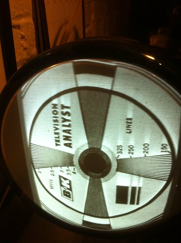 Here are the sync pulses.  Here is the set at what I think would be a normal signal level (half way up the dial on the B&K 1077, which looks to be about the same level coming off my rf modulator on my DVD player). This is the level at which I get horizontal tearing. 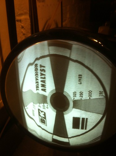 And here are the sync pulses. 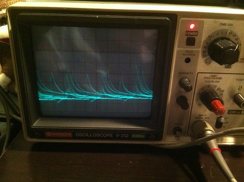 It seems to me that I have a sync problem. Am I off base? I haven't looked into possible causes of the problem, I'll leave that one for tomorrow. 
|
|
#122
02-24-2012, 04:44 PM
|
||||
|
||||
|
I picked up the cabinet from my finisher today and thought I'd share some eye candy. I have no photography experience so it was very hard to show how this cabinet really looks in person but I've picked the best shots out of the many that I took.
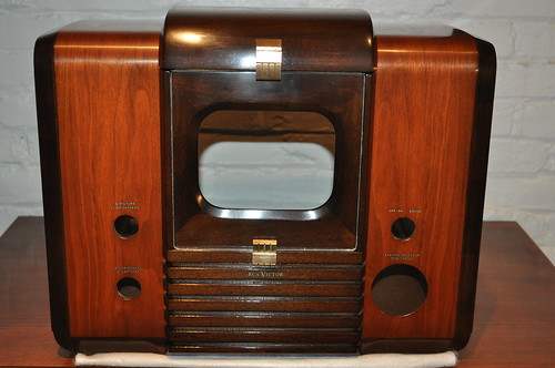 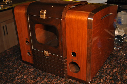 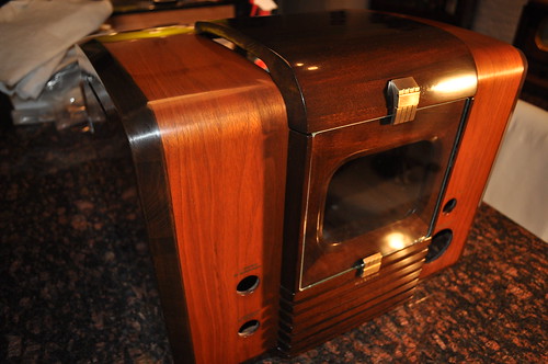 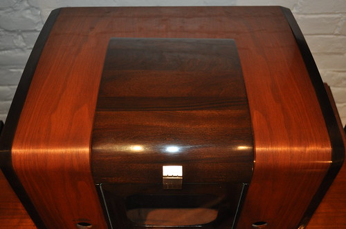 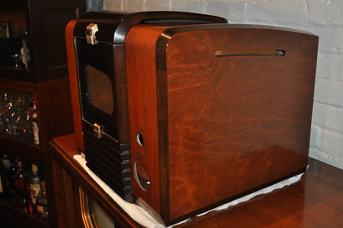  I'm very happy with the way the cabinet turned out.
|
|
#123
02-24-2012, 04:50 PM
|
|||
|
|||
|
Quote:
|
|
#124
02-24-2012, 05:19 PM
|
||||
|
||||
|
That looks very nice!!
|
|
#126
02-24-2012, 06:18 PM
|
|||
|
|||
|
Hey that is a great refinishing job cannot wait to see the finished set entirelypost the pix as soon as you can...Timothy
|
|
#127
02-24-2012, 09:56 PM
|
||||
|
||||
|
Wow, that sure is beautiful!
I did not know one could turn wood into gem stone. 
__________________
Tom C. Zenith: The quality stays in EVEN after the name falls off! What I want. --> http://www.videokarma.org/showpost.p...62&postcount=4
|
|
#128
02-25-2012, 05:27 PM
|
||||
|
||||
|
After much measuring, tweaking, checking, rechecking, etc.. I'm quite stuck on what my horizontal sync problem is
 . I've checked and rechecked the resistors in the sync and horizontal sections and everything checks ok. I've taken voltage measurements in those areas and they check reasonably close as well. I've also swapped the 6SN7GT's (all of which are checked good on a tube tester) around the set and out of the sync/horizontal oscillator sections. I just can't seem to nail where the problem is coming from. . I've checked and rechecked the resistors in the sync and horizontal sections and everything checks ok. I've taken voltage measurements in those areas and they check reasonably close as well. I've also swapped the 6SN7GT's (all of which are checked good on a tube tester) around the set and out of the sync/horizontal oscillator sections. I just can't seem to nail where the problem is coming from. My best stab at the answer is the output of me sync amplifier is really noisy. This is only my best guess, could some one could confirm or steer me in a different direction? The waveform is from the output of the sync amp. 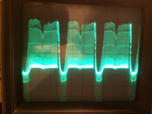 This is the reference from Rider's. 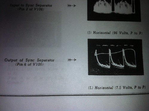
|
|
#129
02-25-2012, 05:57 PM
|
||||
|
||||
|
Does the picture have the same problems if you connect a different signal source (DVD player, whatever)?
Phil Nelson
|
|
#131
02-25-2012, 09:34 PM
|
|||
|
|||
|
You've probably already checked 'em, but there's two more peaking coils, L103 and L104 that you might want to doublecheck for continuity.
If those are good, what happens if you inject video from the B&K at the CRT grid, working back point by point towards the 6H6 detector diode? Need to reduce the output as you move back (to keep the pic from tearing/flagging) and reverse the phase a couple of times (since a tube's plate is always opposite phase from the grid). Also watch for the point at which the 'trailing ghosties' appear (that's assuming they arise after the detector in the video chain). Last edited by old_coot88; 02-25-2012 at 09:37 PM.
|
|
#132
02-26-2012, 11:18 AM
|
||||
|
||||
|
Quote:
I made a template of the crt mask out of card stock to place in front of the screen to get a better idea of what I need to adjust to. I took a video of the set with full video to give an idea of how it looks at this point. The dark diagonal line in the video is not actually on the set, just the video. http://www.youtube.com/watch?v=PTXslUBXsyE The modulator that I'm using is not the best, I hope to replace it soon with a BT modulator just as soon as I find one in my price range. I think my plan of attack on the set is to do a full audio and video alignment according to the procedure outlined in the Rider's schematic. The audio is so bad that there is no sound output currently except some higher frequency FM stations at the low side of the channel selector. I would be doing the alignment under the expert tutelage of a local antique electronic repair expert who has been doing this for decades, and has the necessary equipment for the task. After the set is aligned I can revisit the horizontal instability if need be.
|
|
#133
02-26-2012, 01:07 PM
|
|||
|
|||
|
Hey that's great that you've got an 'Elmer' handy to mentor you through a full sweep alignment and show you first-hand the whys and wherefores of the procedure. Actually the video IF alignment looks pretty spot-on. You might ask him to detune the IFs a bit so you can see the ringing/smearing of fine detail that occurs from misalignment.
Barada nikto, K'laatu 
Last edited by old_coot88; 02-26-2012 at 10:29 PM.
|
|
#134
03-03-2012, 08:33 PM
|
||||
|
||||
|
Much progress today. The aligment went very well and taught me much. The picture, sound, and rf oscilator all needed to be adjusted. The one adjustment that gave the most trouble was the rf oscilator on channels 3 and 4. I also had some trouble with the yoke and ion trap placement to get maximum brightness and a full raster. I had to tweak both the yoke and ion trap extensively to achieve the brightest possible full raster picture. All that being said, the set is back together and looking really good.
Here is a couple pictures of the bottom of the chassis. 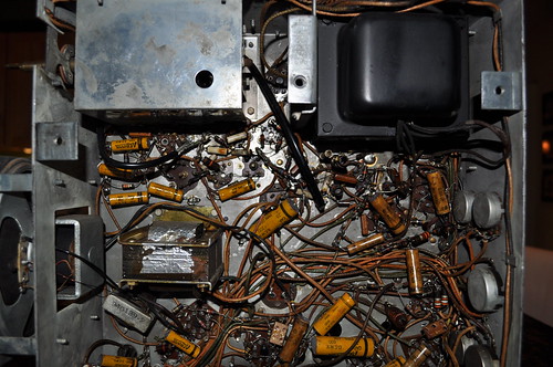  A couple of pictures of the screen with a test pattern. Notice the slight shadow in the lower left hand cornet of the screen. 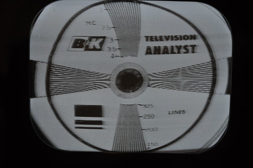 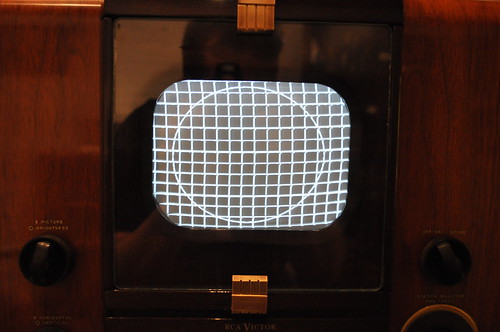 One more shot. 
|
|
#135
03-03-2012, 08:54 PM
|
||||
|
||||
|
Stick a fork in it. Its DONE. EXCELLENT job ! Don't "F!ck" w/it anymore, you're liable to Screw Somethin' Up...(grin) (Redneck Engineerin' 101-Know when to leave Well Enough Alone...)
__________________
Benevolent Despot
|
| Audiokarma |
 |
|
|


 Linear Mode

