
|
|
|
#1
 09-15-2014, 11:19 AM
|
||||
|
||||
|
1956 Packard Bell 21DK1 with raster but no picture
I just joined the community. See my intro forum post for a little more detail if you wish. I got a 1956 Packard Bell TV/radio/turntable, model 21DK1 (I believe the "21" indicates the CRT size) with a 98D1 chassis.
Aside from the fact that I'm sure it needs recapping, the tuner is making poor connection (have to jiggle it around to tune the vcr signal), and while I get raster, I don't get an actual picture from the signal, just a completely white screen. The radio works great though. The turntable appears to work electronically (needle is active) but mechanically it does not. I'm not overly concerned about getting the turntable working, but of course I'd like to get the whole unit in tip top shape. I've purchased the photofact for it as well as "TV Servicing Guide" and "How to Troubleshoot a TV Receiver" books from that era - just waiting for them to arrive now. Of course I've also been researching quite a bit which led me to these forums, among quite a few other resources. Any advice on getting started on this in general or on the picture problem in particular? I do have some background in working on CRT technology because I've been in the classic arcade collecting hobby for years and particularly enjoy repairing the monitors. Of course that means I've never worked with tuners, nor have I dealt with a hot chassis before, as I believe this one is. I haven't looked in detail into the process of recapping vintage TV's but I'm guessing I won't find ready made "cap kits" which are common in the arcade hobby. I'm guessing I'll have to take inventory of what I have from examining the chassis and the schematics. Anyway, I'll shut up now and hope that some of you will be able to ensure I get off on the right foot here. Thanks all! 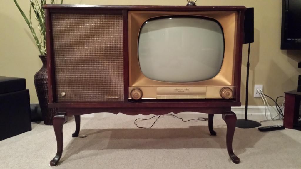 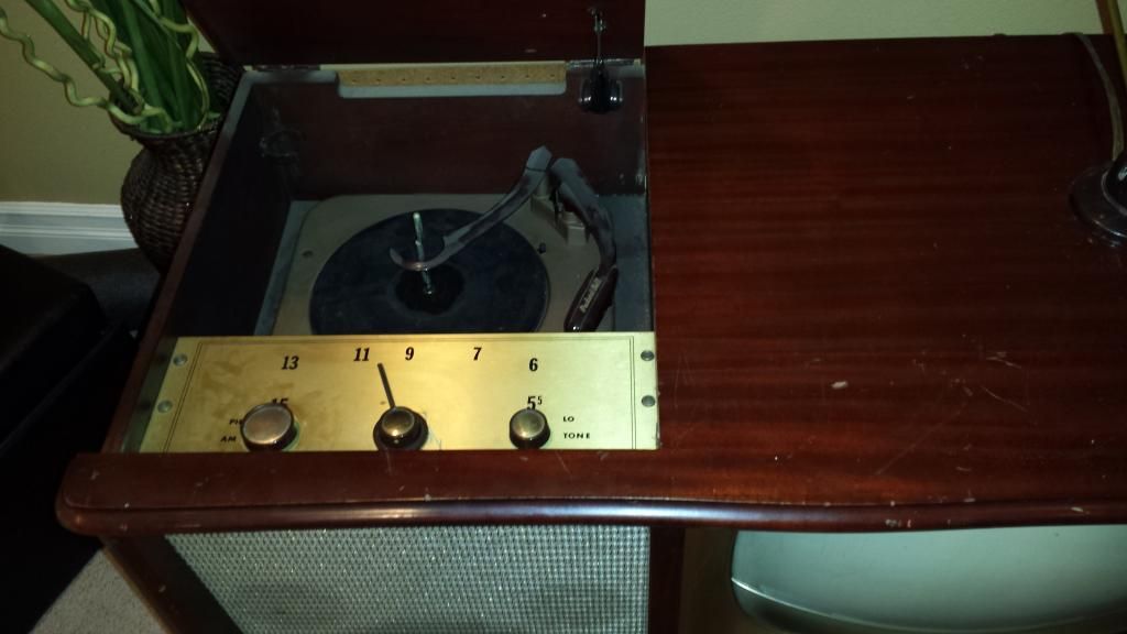 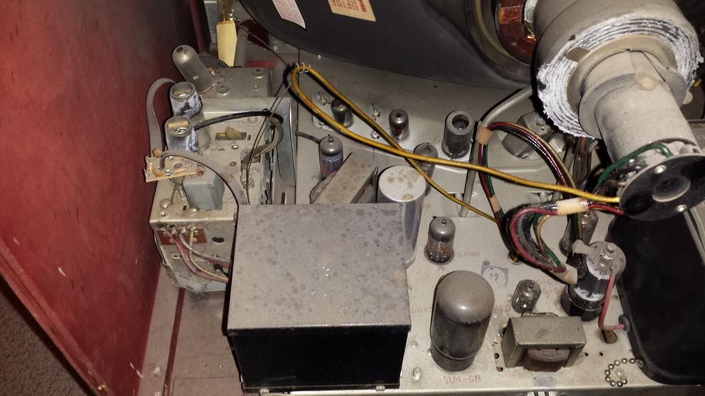  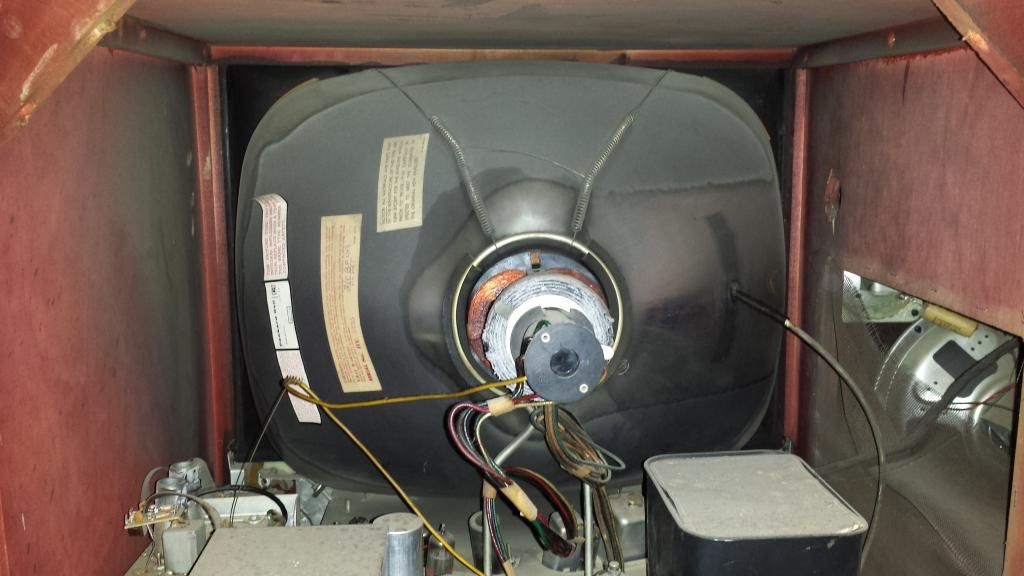 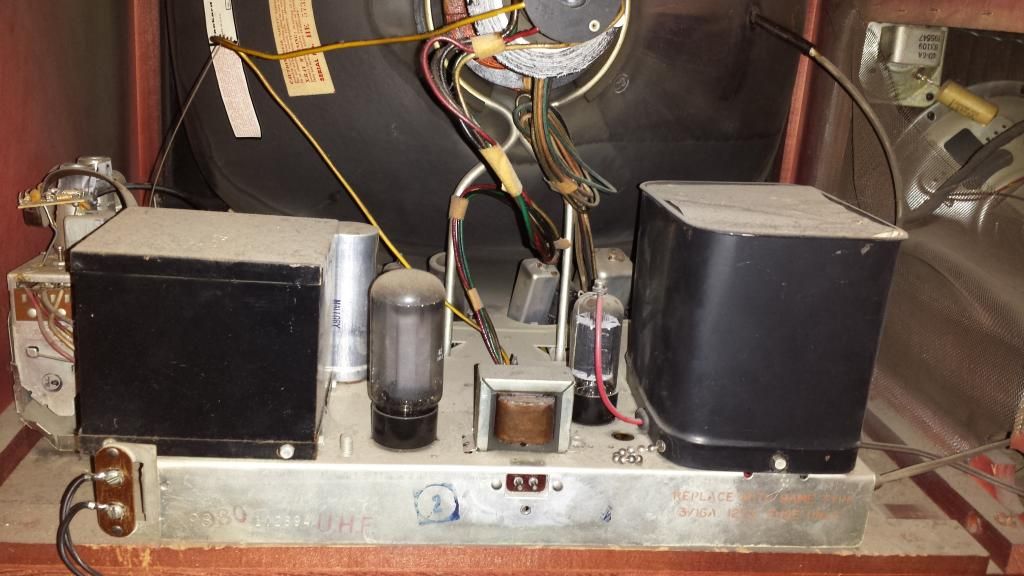

|
|
#2
09-15-2014, 04:52 PM
|
||||
|
||||
|
Yes they do not make capacitor replacement kits for these, but the sam's does have a capacitors section in the parts list. The first 1-about 10 caps will be electrolytics, and will have values between 1 and 500uF and will be rated to handle roughly 10-500V. Replace with a new cap with as much as a 20% (smaller is better) capacitance value difference (if the exact value is unavailable/expensive) and the same or higher voltage rating. The next caps are a mix of types that are virtually immortal, and ones that are usually bad. The bad types will be listed as something like .5 to .0001 and the good ones will be listed as two to four digits like 3900. These you want to try to get as close to value on as feasible, and the same advice on voltage as above is applicable. It is often better to 'shotgun' replace all those caps than troubleshoot individual failures, however since it has been powered on safely I recommend replacing 1-5 at a time and powering up between to check for mistakes.
On your set there are a few possible 'quick fixes' if the original caps are miraculously all still good. The audio is usually picked off the last IF stage on sets of this era so if the video amp tubes are weak or the video detector diode is bad (rare when SS diodes are used) that will give you a blank raster. Another possibility is the AGC tube (if your set has AGC) is bad or the control is miss-adjusted. If you can remove the platter of the record changer there should be a rubber wheel (called and idler BTW) between the motor shaft and where the inner lip of the platter should be. At this age they are usually rotted and need to be rebuilt/replaced. I notice there is also an AM radio on that unit; does it work? EDIT: One more thing sam's is good as long as you beware typos, and remember they do not always reflect all production changes....
__________________
Tom C. Zenith: The quality stays in EVEN after the name falls off! What I want. --> http://www.videokarma.org/showpost.p...62&postcount=4 Last edited by Electronic M; 09-15-2014 at 04:56 PM.
|
|
#3
09-15-2014, 05:55 PM
|
||||
|
||||
|
When you reference "ones that are usually bad" I assume those are the paper caps, which is not something I've dealt with before since the monitor work I've done has been in the era of mid 70's into the 90's, so that'll be quite interesting to me. For the electrolytics I like the approach of stuffing into the cans for the original appearance.
I agree on shotgun replacement, and that's a good suggestion on powering up after a handful of cap replacements. On arcade monitor cap kits I generally do the whole lot but I suspect working on one of these requires a lot more care. As for possible typos, I've read that it's good to note differences between the actual caps and what's in the schematics/parts list. The suggestion I read which sounds good to me whenever there's a mismatch is to stick with what's actually in there if it looks factory, go with the schematic value if it looks hacked, but in either case make note of the difference so you can try the other way if the first choice doesn't work as you expect. This unit was supposedly working recently but if the caps haven't been changed before then I'm sure they're a ticking time bomb. The prior owner was a young lady who is certainly not technically inclined, but beyond that I don't know anything of the history of this unit, other than that it appears to my inexperienced eyes to be well cared for. Thanks for the tips on the possible picture problem. I will definitely check that out once I am ready to start diving in. Thanks also for the tip for the turntable. Yes, the radio works just fine.
|
|
#4
09-15-2014, 05:57 PM
|
||||
|
||||
|
The black box to the left should be a power transformer... The one to the right is the flyback transformer.. Not a hot chassis set...
 SR
|
|
#5
09-15-2014, 06:06 PM
|
||||
|
||||
|
Great! I think I read somewhere that interlocks were used typically for safety on TV's with hot chassis, hence my assumption. I'm also not used to identifying parts on a chassis like this - I'm used to seeing bare isolation transformers and much smaller (non cubical) flybacks. Speaking of which, is it normal to not have a suction cup at the anode or is it missing? I have plenty of suction cups I could stick on there although I always like to err on the side of originality.
|
| Audiokarma |
|
#6
09-15-2014, 06:54 PM
|
|||
|
|||
|
Well, the fact you get a raster, (light on the screen), proves you have high voltage, vertical and horizontal sweep. A Good sign! Are you getting sound from your VCR when you tune to channel 3 or 4, and have to jiggle the knob? If so that means at least the tuner and I.F stages are passing a signal. The reason you have to wiggle the tuner is, that the tuner needs cleaned, probably quite badly. You need to take the cover off the tuner and spray the contacts with electronic contact cleaner, also known as tuner cleaner. The wafer switches or contacts are badly oxidized and is causing intermittent action of the tuner. Rotate the tuner knob as your spray cleaner on the contacts to distribute the cleaner through out the tuner, as it wipes the contacts. The fact you only have raster is probably because no video signal is getting from the I.F stage, and video detector, through and to the video amplifier tube. Look for tubes in the video circuit, AGC and video output. I was trying to see on your picture what tube number is the video output. Looks like it's a 6AQ5, but not sure. Could also be the setting of the AGC control, so try adjusting that. Yes, it could also be bad caps, and most likely you will have to replace them, mainly the electrolytic cans, and small capacitors, especially if they are the old wax caps, or the bumblebee style. Bumblebee caps are black with color code stripes. Nearly all of those caps are or will become leaky, and may even pop, smoke or blow up. Not very hard to do, if you just take one at a time, and know how to solder. Yes, It's time taking, but worth it. The record changer probably needs to be cleaned, lubed, and the idler wheel replaced. Many times also you have to take apart the small motor, and clean and lube the bearings as well. Honest, it's an easy job, just keep track of how things go together. I usually use a light weight oil for the motor bearings, and also on the spindle bearings. Sometimes you can clean up and restore the rubber idle wheel with a rubber cleaner called vita-drive, or any type of rubber restorer made for that. Also you may have to replace the cartridge and needle, if sound is weak, distorted or needle skips across the record. Just find the part number on the cartridge and Google it. There are still a lot of parts to be found, and I also find a lot of capacitors on e-bay. Must say that is a very nice looking relic, and should be well worth restoring. Looks like it has some awesome size speakers, from what I can see from the grill cloth. Too bad you not near Omaha NE, I'd be glad to help you with it.
|
|
#7
09-15-2014, 07:19 PM
|
||||
|
||||
|
Yes was referring to paper caps...Be wary some masquerade in plastic shells either tubular or the sneaky ones that look like (and sometimes are listed like) the *reliable mica dominoes. *Mica caps do tend to fail in sweep circuits due to the stress those circuits tend to place on them.
The right metal can is just a safety cover/electrical noise shield over the flyback and HV rectifier...You can remove it to replace that tube and perform other service tasks if you wish. Interlocks invaded nearly ALL radios and TVs before the 60's, and TVs were early adopters due to fear of the potential dangers HV. Some 50's sets had suction cups, but it was not until ~1960 that it became close to standard. There should be a shield on the tuner underside that can be removed to access the contacts so that you can clean them (your initial post suggests to me that they are dirty).
__________________
Tom C. Zenith: The quality stays in EVEN after the name falls off! What I want. --> http://www.videokarma.org/showpost.p...62&postcount=4
|
|
#8
09-15-2014, 07:21 PM
|
||||
|
||||
|
Yes, I get sound and I realize I need to clean the contacts.
I'll try adjusting the AGC, and speaking of which, 2 other front access technician controls are "pix lock" and "drive". I'm guessing "drive" is equivalent to the r/g/b drive controls on a color crt but what about "pix lock"? And this reminds me... it's a shame that user manuals seem to be nonexistent for vintage tv's. Not that it would go into detail on technician controls but still, a manual would be cool to have. I don't know yet what the left outer knob does (inner main knob being power/volume). Here's a closeup of the tube diagram. I'm not sure which one you're looking at. I see 6AQ5 but the one I'm seeing is for audio (upper right). 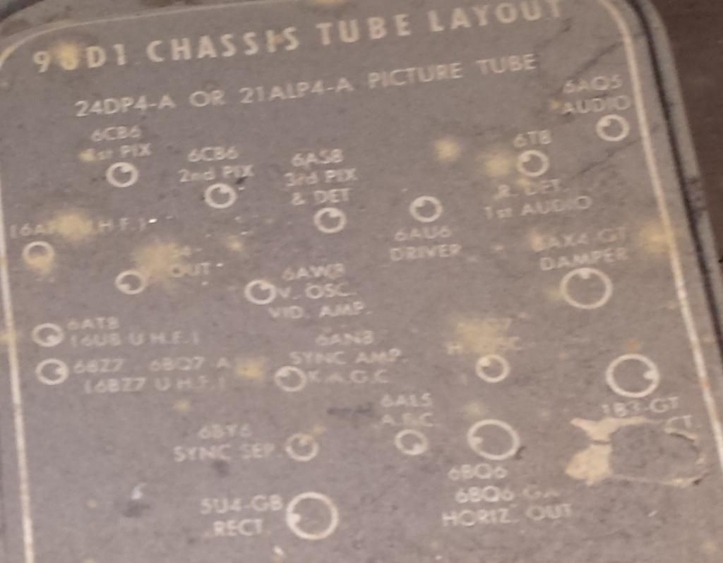
|
|
#9
09-15-2014, 07:36 PM
|
||||
|
||||
|
I just tried adjusting the AGC but no luck. Also, it was adjusted all the way clockwise which suggests to me that perhaps one or more capacitors have drifted out of spec and as a result the AGC can no longer be set correctly. I'll also check the tubes once I know a little about doing so... the only kind of tube I know how to check is the CRT (I have a rejuvenator).
Thanks to all of you for the input. It is really helpful for me in coming up to speed!
|
|
#10
09-15-2014, 07:50 PM
|
||||
|
||||
|
The 6AW8 is definitely the video tube, the 6AU6 'driver' tube could also be a video amp.
The drive control you mention is more likely horizontal sweep drive, and should not be messed with until you read the service adjustment procedures in the sam's. AGC can be funny; if you set it too high you can mess things up as well (no synch, over contrasted or no video.)
__________________
Tom C. Zenith: The quality stays in EVEN after the name falls off! What I want. --> http://www.videokarma.org/showpost.p...62&postcount=4
|
| Audiokarma |
|
#11
09-19-2014, 12:12 AM
|
||||
|
||||
|
Got the technical info I ordered today so I've started doing a little reading and hopefully I'll get some time to start digging in this weekend. Photofact, "TV Servicing Guide Arranged By Trouble Symptoms", and "How to Troubleshoot a TV Receiver".
|
|
#12
05-12-2015, 10:49 AM
|
||||
|
||||
|
Finally recapped the chassis and I get a picture now (pic attached) but it still needs a little work...
I was getting sound before the recapping but now I'm not, though the radio produces sound. So I'm not sure if it's possible that I messed something up when recapping (though I was very careful) or if the lack of sound is somehow coincidental to just having recapped. I'll have to start tracing the audio circuit. Also I need to clean the tuner (and controls) but I'm having trouble finding a good guide for doing so. I want to do a thorough job. Right now it can be a little tricky to get the channel selector in the right position to tune the signal. Pic of tuner attached. I'm curious about trying to dial in the perfect picture. Since I'm not finding a focus adjustment, how is focus achieved/adjusted on sets of this vintage? The focus isn't bad by any means but I'm not ready to call it perfect yet either. I'm also curious about adjusting the width. On arcade monitors of the 80's/90's there's usually a width coil for adjusting width. How was it done on these? Finally, are there any other remaining suggested maintenance steps when doing electrical restoration on sets like this? I'd like to be as thorough as practical to ensure it's running optimally. Happy to have gotten this far! 
|
|
#13
05-12-2015, 01:34 PM
|
||||
|
||||
|
Its a turret tuner so you can hold a big eraser on the little
dots that are the contacts. While doing so make a bunch of full turns on the tuner. Often thats all you need to do. DO NOT get near the UHF section, its the part with the gang tuning cap. P-B made some nice sets but in latter years relabeled GE sets. Also saw some Panasonic mid level audio with there name. Real P-B's quite rare sets in New England. 73 Zeno 
|
|
#14
05-13-2015, 01:41 AM
|
||||
|
||||
|
Yeah, I have no real need to worry about UHF since my main concern is hooking an external source to channel 3 (or 4). They cleaned up nicely though - the channel selector is working great. Thanks for the advice. IIRC Packard Bell was bigger on the west coast? Another forum member right here in the Portland area has this same console. But OTOH it seems like info on this unit is hard to come by if not impossible.
Now I'm trying to study and trace the audio circuit to figure out why the radio works but the TV's audio doesn't. It used to before recapping so obviously that work is suspect but nothing obvious so far. Unfortunately the schematics that are available for this are just for the standard TV and mine is a console so the schematics are missing all the additional circuitry. Anyone have a suggestion for replacing the plastic circular wedge piece that squeezes between the yoke and the CRT neck? Since my TV has been disassembled for months, I suspect it got misplaced and I now fear it's been thrown out. Perhaps something people would have in their spare parts bins if I post a WTB? Or can they be purchased somewhere?
|
|
#15
05-14-2015, 08:50 AM
|
||||
|
||||
|
Almost any TV from mid 80's on will have rubber yoke
wedges. There are 3 of em around the edges. It looks like the yoke cover ( part with the centering rings) is about to turn to powder so be careful of that. 73 Zeno
|
| Audiokarma |
 |
| Thread Tools | |
| Display Modes | |
|
|


 Linear Mode

