
 |
 |
|
|
Thread Tools | Display Modes |
|
#1
|
||||
|
||||
|
Ever wanted to build a tube Video modulator?: the Custom Electronics corp model 3A
At the October ETF swap meet I bought this tube video(only) modulator.
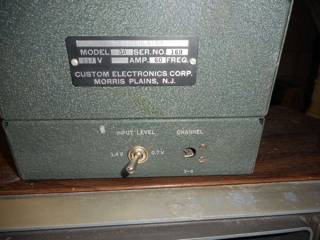    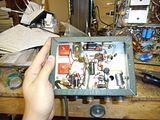 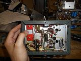 I tested it out late last night and was rewarded with a basically perfectly functioning unit despite 4 original lytics, 2 foil caps, and original seleniums. I was able to get roughly 50-75' of range with it driving a simple pair of rabbit ears (it'll likely do better with a tuned dipole). A good look at the circuit reveals no odd ball/hard to source parts so this could likely be copied by hobbyists. It would appear that perhaps all that would need to be made is the osc. transformer, and that looks like a walk in the park to make....I'd wager an experienced Ham or engineer could easily modify the osc. xfmr to work on channels other than 3 and 4, and the unknown value RF chokes likely are not critical in value..... Below is the schematic. 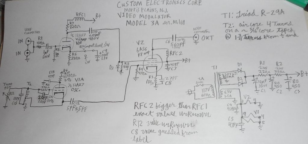 All that it could use is an audio modulator section....I'm open to ideas on how to implement it. I initially thought the two tied together inputs may have been for a separate audio modulator that would mix with the video, but that seems unlikely considering that they used to daisy chain many devices along some video lines back then, and the dual input jacks are likely for that rather than two different input devices.
__________________
Tom C. Zenith: The quality stays in EVEN after the name falls off! What I want. --> http://www.videokarma.org/showpost.p...62&postcount=4 |
|
#2
|
||||
|
||||
|
Update:
Replaced C1,C9,C10 since those were open, leaky and leaky respectively. B+ increased from 85V to 100V with the cap change, and reception range has improved. If I feed it's output through my SKL tube TV band RF amp the range is comparable to a Blonder Tongue BAVMZ series. Decided to measure the fine tuning control on the modulator and discovered it is not a pot, but rather a 50pF trimmer cap. Up dated schematic below. It works great, but after about half an hour prominent hum started leaking into the signal so I may end up recapping it further and nixing the seleniums. Here is a pic of the test set up running a Monty Python VHS as the signal source.  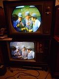 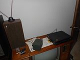
__________________
Tom C. Zenith: The quality stays in EVEN after the name falls off! What I want. --> http://www.videokarma.org/showpost.p...62&postcount=4 |
|
#3
|
||||
|
||||
|
Looks nice! I would definitely complete the recap, especially the PS filters. Dumping the seleniums a good idea as well.
Adding sound will be a bigger project, as you will need to add a separate FM oscillator to generate the audio carrier, then combine the 2 carriers together in the output RF amp. |
|
#4
|
||||
|
||||
|
Quote:
You could disconnect the 2nd video input jack and use that for the audio input.
__________________

|
|
#5
|
||||
|
||||
|
Quote:

|
| Audiokarma |
|
#6
|
||||
|
||||
|
Quote:
I've already tested the osc. section without the biasing resistor network or 27pF cap (just an all out basic Hartley osc.).
__________________
Tom C. Zenith: The quality stays in EVEN after the name falls off! What I want. --> http://www.videokarma.org/showpost.p...62&postcount=4 |
|
#7
|
||||
|
||||
|
Neat project!
I wonder how linear the modulation is - will be interesting to see if you can avoid 920 khz audio/chroma beats when the 4.5 MHz is added. This was the bane of early transistor modulators for VCRs and was the reason the 4.5 MHz injection was kept near the minimum level acceptable to receivers. Another thing you may want to try is replacing the 220 ohm and switched bypass for 0.7V / 1.4 V video level with a pot, to get an adjustable modulation level. |
|
#8
|
||||
|
||||
|
Had the WORST day in a while today. Spent 5 hours at home depot statring with culling unwarped plywood for a sub floor for the hard wood the folks are laying down, followed by waiting for a rental truck to return to a DIFFERENT store since the one at the store we were at blew a brake line, and they did not tell us it was out of commission when we called ahead......
I came home to a funny burnt electrical smell with no localized source. Immediately after getting the gremlins that I'd been fighting for a couple of days out of my osc. sub chassis (they of course go running around the house looking for other electrical victims) I change the filter on the furnace and notice the burners running without the fan....I wait a minute and conclude the fan (which was fine when I got home) has died. Opening the panel on the furnace revealed one of the fan motor wire nuts BURNED open. When I was examining the panel my breath put the pilot flame out, and after fixing the motor wiring (no clue why it burned open in the first place) the fan work but no flame in the furnace and I can't manage to manually relight the pilot (this is the first time I've ever opened up and worked on a furnace).......The darn thing made me miss most of my late Saturday TV shows too (at least I did record them). And when I went to watch my CCI daily driver console did not produce HV (the darn H out tube socket heater contacts went open again after ~1 year of trouble free operation). Quote:
My main problem once I built the sub chassis was non-sinusoidal output....I had double peaked pulses at best a total mess at worst. I was initially working using only my freq counter and confounded by the frequency rising and falling while tuning my trimmer cap in only one direction. Once I added the scope to the mix it became apparent the wacky waveform was fooling the counter. I had to add a 430pF feed back cap from the output of the 6J6 amp section plate to the coil side of the 27pF cap to make it a clean sine wave (it also improved output strength). I know it is working at 4.5MHz and mixing with the agile modulator correctly since tuning it above and below 4.5Mc would silence the received audio static in the neighborhood of 4.5. Pay no mind to the static in the TV picture....The tuner is dirty (or something like that) and that TV set does that on all other signal sources I have including good ones other sets receive crystal clear. If and when I get audio working decently I'll repost my schematic with all the audio mods added to it. The video modulator on it's own seems to be having video flicker/horizontal tearing (noticed this before building the osc) that I need to check....Though it could just be intermittents in that flaky CCII I'm tuning it's signal with. 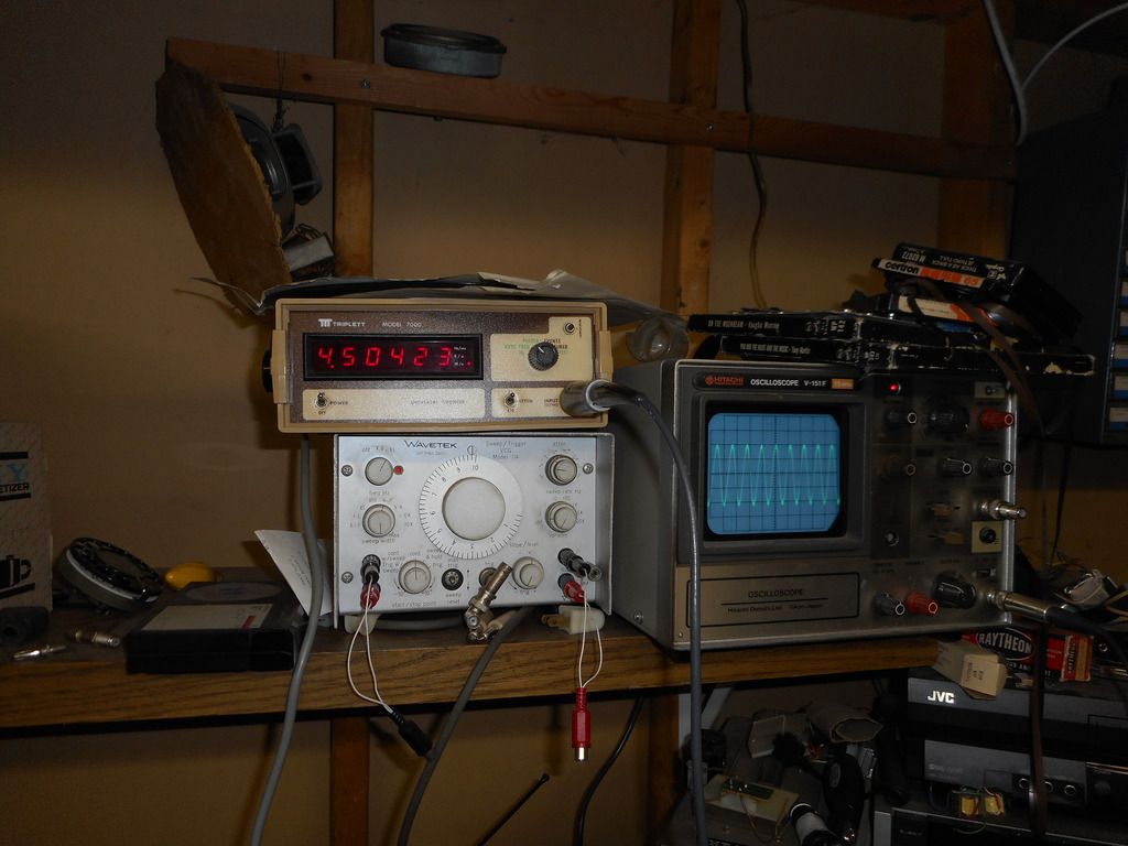   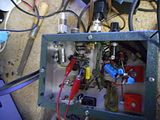 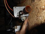 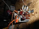 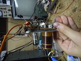 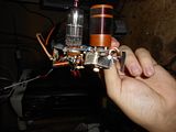
__________________
Tom C. Zenith: The quality stays in EVEN after the name falls off! What I want. --> http://www.videokarma.org/showpost.p...62&postcount=4 |
 |
| Thread Tools | |
| Display Modes | |
|
|