
|
|
|
#31
 02-22-2018, 06:25 PM
|
||||
|
||||
|
When you say destroyed the feed through cap do you mean cracked the dialectric ? If so just leave it alone as long as it's not shorting to ground. I've never replaced one or seen one that needed replacing but I've seen a few that have been cracked but caused no noticeable issue. I think you would cause much more damage trying to replace it. Tread very carefully around the tuner and IF strip. Small value ceramic and styroseal caps are generally very reliable. A full IF alignment is not for the faint hearted.

|
|
#32
02-27-2018, 10:23 PM
|
||||
|
||||
|
No Sharp Points?
First, regarding the feed-though cap: When I say "destroyed," I mean it. Fortunately, I studied sweep alignment for two years at the Sorbonne. Unfortunately, this is not a French television set. But seriously, there's no need to despair. I want to get rid of this set as soon as I'm finished playing with it. The only way I can fail is by not doing anything at all. So, the project proceeds regardless of the outcome.
No Sharp Points? I have a healthy degree of anxiety about high voltages. Somewhere in the Sams and Rider information there's a note to avoid sharp points in solder joints on high voltage lines. I'm not sure why, but I copied the original bulky, rounded connection to the base of the HV rectifier. What might happen if there was a sharp point? I also made the high voltage cable a foot longer (temporary) with plenty of insulation at the connection. 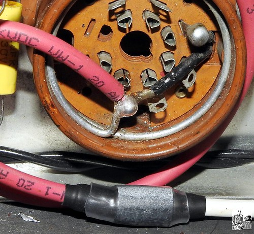 I envisioned a wooden cradle to keep the CRT securely positioned, but I found a more practical option. 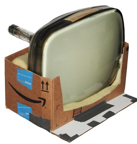 I found one glitch in the tuner (besides the feed-through cap). There's no connection to the plate of the 6BC5. The circuit is open somewhere in the area shown below.  I was getting inconsistent resistance readings in this circuit for days until I found one defective solder joint. After repairing it, there was still no connection to the coil or 110V line. 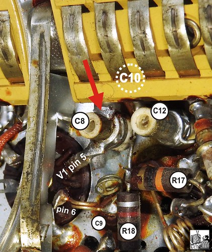 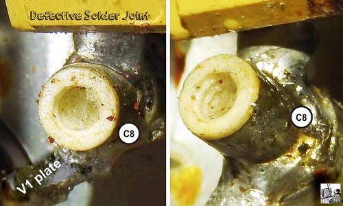 The open circuit must be between the two left contact strips in the picture, but the coil and connection are neither accessible nor visible.  It looks to me that if I can remove the single rivet, that the yellow plastic mount will slide off of the contact strips, and I'll have access to whatever is hiding behind it. Before I attempt this, does anyone have a better suggestion? Thanks, Henry "The Destroyer of Caps."
__________________
Winky Dink Damn the patina, Full speed ahead!
|
|
#33
02-28-2018, 01:48 AM
|
||||
|
||||
|
I can't answer your tuner questions, but regarding rounded solder joints in high-voltage areas, spiky joints could encourage corona discharge (https://en.wikipedia.org/wiki/Corona_discharge), which may lead in turn to high-voltage arcing & sparks (never a good thing).
That CRT cradle is ingenious! More secure than my usual teetering pile of old bath towel or foam bits. Phil Nelson Phil's Old Radios https://antiqueradio.org/index.html
|
|
#34
02-28-2018, 10:52 AM
|
||||
|
||||
|
Thanks, Phil. I probably would have done the bath towels if I'd thought of it.
Do you have any thoughts on compensating or replacing a missing feed-though capacitor? It's in the 6.3V line into the tuner.
__________________
Winky Dink Damn the patina, Full speed ahead!
|
|
#35
02-28-2018, 04:16 PM
|
||||
|
||||
|
Quote:
jr
|
| Audiokarma |
|
#36
02-28-2018, 05:02 PM
|
||||
|
||||
|
No Surprises Behind the Yellow Thing
Thanks for the suggestion on the missing capacitor.
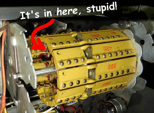
I was wrong about sliding the yellow plastic thing off the contacts--the hidden ends of the contacts are anchored to the plastic. 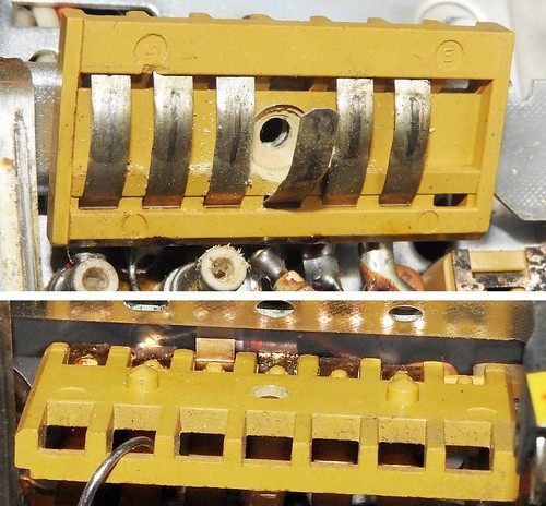 I don't know what I expected to find back there, but I didn't find it. There were no hidden surprises. So I stuck it back together. Next thing is to reassemble the parts and run some electricity through the set.
__________________
Winky Dink Damn the patina, Full speed ahead!
|
|
#37
02-28-2018, 10:12 PM
|
||||
|
||||
|
Well, Duh!
After reassembling the tuner, I finally found the missing connection and coil.
__________________
Winky Dink Damn the patina, Full speed ahead!
|
|
#38
03-03-2018, 12:34 PM
|
||||
|
||||
|
Will Wonders Never Cease?
Will wonders never cease? I got all the parts in the right places, and it works with a DVD player. I positioned the yoke retainer, yoke, and ion trap according to the dirty/clean lines on the neck, and the centering magnets according to my earliest photos. Beyond that I only had to adjust the outside controls and figure out that the DVD input plays on channel 13.
This is my setup: Isolation transformer, variac, chassis, CRT, mirror. A couple of questions on this photo. 1. This doesn't have a rubber cup guarding the anode connection. Is this unusual? 2. What is this chain for?  I posted a short video on Flickr. It only works for me when I start my computer. Then, after one or two plays it won't work until I restart the computer. Maybe it'll work for you. https://flic.kr/p/23KQVaY I took a couple of screen shots this morning. 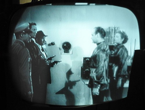 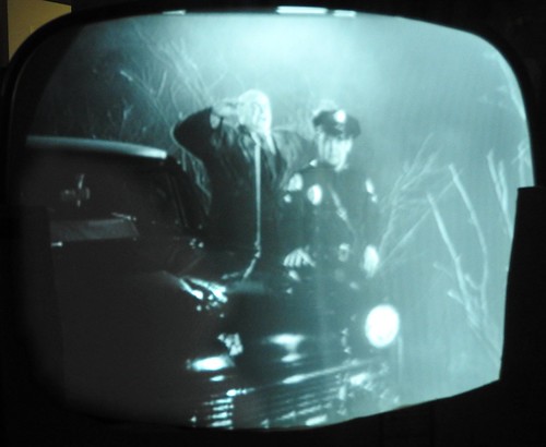 I'll try connecting an antenna, but as it stands this is a gratifying success for me. Thanks for all the help that made it work. If you can guess both films you get extra credit.
__________________
Winky Dink Damn the patina, Full speed ahead!
|
|
#39
03-03-2018, 02:38 PM
|
||||
|
||||
|
Congratulations!
 Quote:
Is there a place on the hv cage cover to attach the other end of the chain? Video works fine on my iPad. jr
|
|
#40
03-03-2018, 03:22 PM
|
||||
|
||||
|
I should've mentioned that it is attached to the HV cover.
__________________
Winky Dink Damn the patina, Full speed ahead!
|
| Audiokarma |
|
#41
03-03-2018, 03:26 PM
|
||||
|
||||
|
Correction: I just looked at the cabinet and noticed the channel selection marker. It's not showing the DVD on channel 13. It is actually on 3.
__________________
Winky Dink Damn the patina, Full speed ahead!
|
|
#42
03-07-2018, 10:41 PM
|
||||
|
||||
|
Shocking Discovery
Before doing the cabinet reinstallation I did final adjustments on the ion trap, centering magnets, horizontal drive, vertical linearity and height. I had a good, stable picture. But when I moved the CRT, the yoke and its retaining ring came loose. The rubber retaining was too age-hardened to grip the glass neck or the yoke.
I soaked the rubber ring in wintergreen oil overnight. I reinstalled the yoke, and the retainer was supple enough to keep it firmly in place. But with power on, I got zapped when I tried to reposition the yoke. I poked around a big and found that one (only one) of the centering rings was hot--voltage too high to read on my multimeter.  From looking at the yoke, I can't see how there can be any electrical connection to the centering magnets. I'd previously handled the magnets with no problem. I took everything apart again, rechecked the resistances and found an open circuit as shown here. 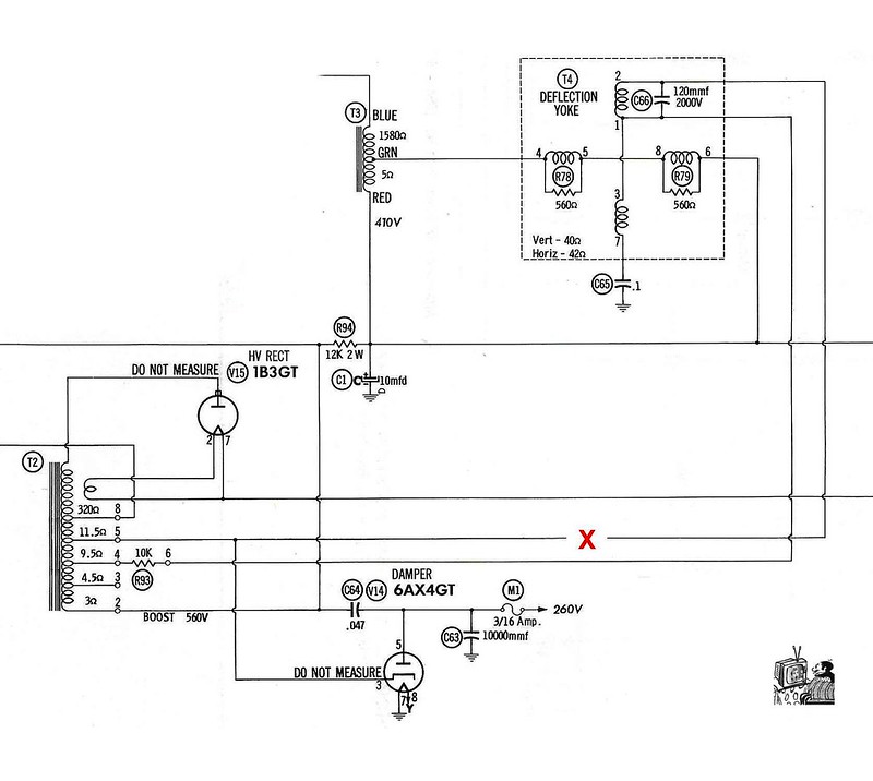 I corrected that, put the yoke back on, but found the magnet-electrocution risk was the same. How and why do I have like a thousand volts at one of the centering magnets? The whole schematic is at this link. It's hard to read online, but quite legible if you download it at the original size. https://flic.kr/p/24Z7cYP Thanks for looking. - Henry
__________________
Winky Dink Damn the patina, Full speed ahead!
|
|
#43
03-08-2018, 05:25 PM
|
||||
|
||||
|
I would try touching it with a grounded screwdriver briefly to see whether it's just leakage or a hard connection to HV. I suspect leakage of some sort. I can't imagine how a centreing ring could come into contact with anything.
|
|
#44
03-08-2018, 10:56 PM
|
||||
|
||||
|
I Think I Found the Problem
Actually, I think the centering ring built up a static charge. I focused on the centering ring because it was the only conductive surface I was aware of contacting, and it made the multimeter flash strange readings like FFFF for overflow.
I think this the culprit: 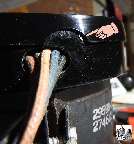 The exposed rivet is at the lower side of the yoke, hidden from my view. It connects the "DO NOT MEASURE" voltage to coils. I insulated all the potential conductors which I might accidentally contact and I was still wary of the centering rings, so I made handles with epoxy putty. 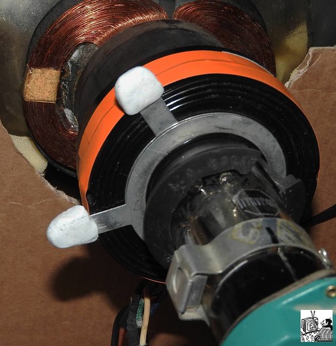 Now I'm proceeding with adjustments without getting electrocuted. Thanks for your thoughts on the matter. - Henry
__________________
Winky Dink Damn the patina, Full speed ahead!
|
|
#45
03-11-2018, 04:16 PM
|
||||
|
||||
|
Nice work Henry.
|
| Audiokarma |
 |
|
|


 Linear Mode

