
|
|
|
|
|
#1
 04-09-2016, 01:49 PM
|
||||
|
||||
|
Drive line Question
I am completing the recap of the ctc4B chassis for my Cheltenham.
I was plagued with a strong vertical bar in the center of the screen which I believe is referred to as a "drive line" Adjusting the horizontal drive control to minimum would not make the drive line go away. As it turned out the 6CB5 HOT (which tested very good) was the cause. I had to try 3 NOS tubes before I found a tube that cured the drive line issue. Just by luck one of the NOS tubes made the drive line disappear. I am not terribly well versed from an electronic theory standpoint. I know that there are many of you who understand electronic theory way better than I do. Can someone explain what causes the drive line, and what the reason was that I had to try several known good NOS tubes to find just the right one to make the drive line go away? Any enlightenment would be gratefully appreciated.
__________________
Vacuum tubes are used in Wisconsin to help heat your house. New Web Site under developement ME http://AntiqueTvGuy.com 
|
|
#2
04-09-2016, 06:58 PM
|
||||
|
||||
|
I am not good at pure engineering theory. Just bench
theory, there are places for both. To us a drive line was a bit of hoz fold over caused by the H. osc or H out. Usually on the right IIRC. You may have had a snivet, IIRC caused by oscillations in the H out tube. Reason for multiple tubes either the tubes were low quality or maybe something else is off a little. Look to the screen grid decoupling cap. Again IIRC another cure was a magnet around the H out tube. Very common in the olden days. 73 Zeno 
|
|
#3
04-09-2016, 10:49 PM
|
||||
|
||||
|
Not sure, but checking the H oscillator/driver may be worthwhile in case it is contributing to the touchiness of H out selection.
|
|
#4
04-09-2016, 10:57 PM
|
||||
|
||||
|
It may have been Barkhausen interference, I've usually seen it on the left third of the screen, but I had an RCA with what I'm assuming was Barkhausen interference dead center. It was a large bright noisy vertical line. Changing the HOT fixed it.
|
|
#5
04-10-2016, 01:29 AM
|
||||
|
||||
|
Quote:
Hope someone else can chime in with more details...
|
| Audiokarma |
|
#6
04-10-2016, 02:51 AM
|
||||
|
||||
|
Quote:
__________________
Tom C. Zenith: The quality stays in EVEN after the name falls off! What I want. --> http://www.videokarma.org/showpost.p...62&postcount=4
|
|
#7
04-10-2016, 07:21 AM
|
|||
|
|||
|
Had the same problem with the ctc7. It was a burned up horz lin/Eff coil. Did you replace the damper tube?
|
|
#8
04-10-2016, 09:43 AM
|
||||
|
||||
|
I have several books and read more than a few HO tube data sheets that talk about it and what causes it, but never seen it in real life on any of my sets. But then I'm a nazi when it comes to horizontal circuit set up and adjustment, so maybe my being anal about it is why it hasn't come up. A few data sheets I've read (for compactrons) state that applying a small positive (~30 volt) potential to the beam forming plates can counteract the phenomena, but obviously this is not possible in tubes having the beam forming plates tied to the cathode. I've heard of the ion trap trick as well, and even encountered a chassis with a seemingly factory installed magnet around the HO tube. Common wisdom these days says go tube rolling till you find one the chassis likes, but not everyone has piles of sweep tubes laying around their house.
__________________
Evolution... 
|
|
#9
04-10-2016, 11:05 AM
|
||||
|
||||
|
Read here about "reaction scanning" describing the phases of the horizontal scan process on a CT-100 (and likely most other tvs with a flyback transformer).
http://www.earlytelevision.org/Deksn...implified.html I suspect that the "drive line" is visible when the transition between the various scan states is not correct due to leaky caps out of spec resistors, weak damper or HO tube, miss adjusted grid drive, while BO is a self oscilation of some HO tubes, which can indeed be stopped by a magnetic field from an ion trap mounted on the tube. Two different causes of lines, IMHO. jr
|
|
#10
04-10-2016, 02:41 PM
|
||||
|
||||
|
Exactly. Two different things. Both hard to describe. A drive line
as we knew it was a true failure. Often seen on SS sets when the 1.5 ohm base resistor changed value. It has a fold over look just like vert fold over. You can see backwards elements of the scene moving about in a apx 1 inch area. Damage WILL occur eventually. Snivets did not distort the pix geometry wise. They come & go & are usually narrow ( < 1/2 inch ). May or may not go top to bottom. Usually have squigglys in them. Move around sometimes. They also radiate & can bust up a lesser set like a GE, Emerson etc. One of our by-outs was a wanna be radio shack. They loaded this poor cat with thousands of tubes. Al were IEC service master, Ratheon & Lindals. Every HO tube gave snivets........ We used them in "last time" repairs on junkers to save the customer $$. 73 Zeno Quote:
|
| Audiokarma |
|
#11
04-10-2016, 03:26 PM
|
||||
|
||||
|
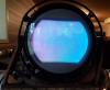
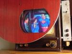
Yes, a horizontal "drive line" arises from a different cause and it looks different than a Barkhausen line.
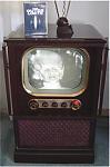
A "drive line" is white and it's caused by excessive drive in the horizontal output tube. Here's an illustration from one of my TV books: 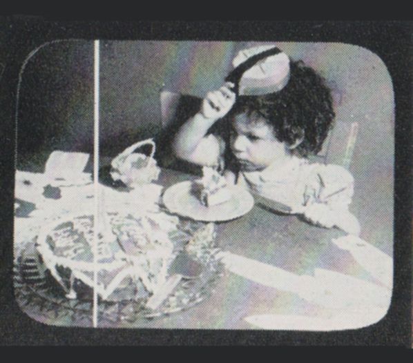 TV literature often tells you to watch for the "drive line" while adjusting the horizontal drive control. Turn it up until the line appears, then turn it down until the line just disappears. A Barkhausen line is dark. One of my books describes Barkhausen interference as "a parasitic oscillation in the horizontal output stage, radiating to the antenna input terminals of the receiver." The name alludes to similarities in a Barkhausen-Kurtz ultra-high frequency oscillator. My Hallicrafters T-67 had a classic case of Barkhausen interference: the squiggly vertical interference line in the left part of this screen, going right past the woman's nose: 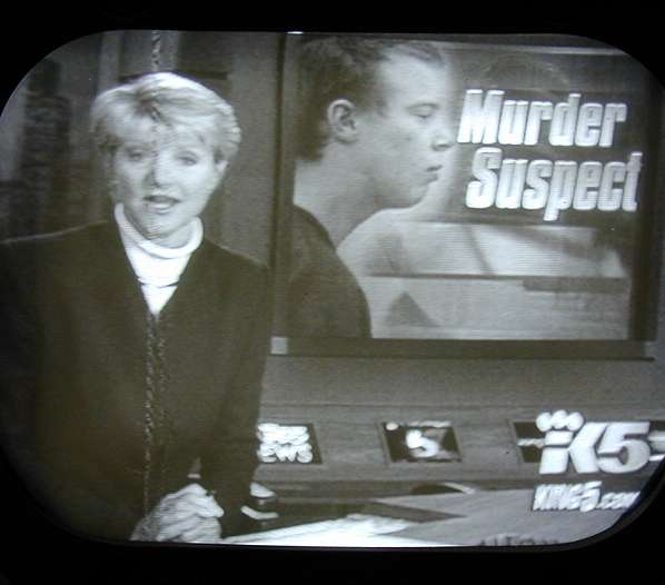 I cured it by replacing the 6BG6 horizontal output tube. Swapping a used 6BG6 didn't do the trick, but a new HOT cured it for good. (Footnote: all of those tubes tested equally "good" on my tube tester, but that's irrelevant in these cases, since the tester tells you nothing about oscillation.) Here's more: 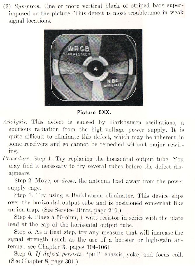 The "Barkhausen eliminator" mentioned in that book looks like a miniature ion trap magnet. My DuMont RA-103 has a small permanent magnet mounted in the HV cage near the HOT, presumably to minimize Barkhausen interference.  I don't know if the RA-103 was especially susceptible to Barkhausen interference, or if that magnet was just typical Dumont over-engineering. My newer RA-113 has no such magnet, so perhaps it was dropped as a nice-but-not-necessary feature, just like the RA-103's B+ delay circuit that required a relay and extra tube. Regards, Phil Nelson Phil's Old Radios http://antiqueradio.org/index.html
|
|
#12
04-10-2016, 05:39 PM
|
||||
|
||||
|
Great discussion guys. Thanks!
To more enlighten you as to if it's drive line or barkenhausen: The line looks like the "drive line" in the photo above. It gets stronger as you turn up the H drive control, and get dimmer when you turn it down, however it would not go away with the control at minimum. All caps were replaced so it is probably not that, however I did not check voltages on the HO tube to see if they were in line with what is expected. In any event a good NOS Sylvania cured the issue, but several "International" brand imports had the same issue as the original defective tube which was also a Sylvania. My biggest question is why the difference between various NOS tubes? That just dosent make much sense. You would logically think there has to be an underlying cause as to why several new tubes would not work properly. FYI the thing that led me to replacing the HO tubes in the first place was that I noticed the getter flashes looked a bit off color, a tad bit brown around the edges of the flash. So I took a chance in swaped tubes and got lucky with the NOS Sylvania. BTW, the line was right in the center of the screen left to right and ran all the way top to bottom
__________________
Vacuum tubes are used in Wisconsin to help heat your house. New Web Site under developement ME http://AntiqueTvGuy.com Last edited by ohohyodafarted; 04-10-2016 at 05:42 PM.
|
|
#13
04-10-2016, 08:56 PM
|
||||
|
||||
|
Silly thing is you can probably put the 'bad' tube in another set, and the line won't be there. Just one of those things with TVs, gotta roll tubes and see what it likes.
__________________
Evolution...
|
|
#14
04-12-2016, 10:28 PM
|
||||
|
||||
|
The retrace time in transistor sets probably got shorter over time as higher-voltage transistors became more readily available, but I don't know actual numbers. Excessive overscan was a constant complaint of Consumer Reports over the years. The excess was necessary in tube sets because of the variability in components including tubes, and the unregulated power supplies. Later solid-state sets with regulated supplies and much less variation due to the H output device could reduce the overscan without danger of producing black edges. Before the regular use of letterboxing, manufacturers avoided underscan at all costs because black edges would bring warranty claims.
Regarding variation due to the output device: tube HO's have significant voltage drop at peak current (50 to 100 volts), whereas a transistor will have a reliable saturation voltage on the order of a volt. Moto had trouble with its first transistor sets in New Orleans due to this: humidity would infiltrate the flybacks as the sets were in the warehouse. A tube (or 4-tube hybrid) set would refuse to draw terribly excessive current, and would heat up the flyback slowly enough on first use that the moisture would be driven off safely. The high voltage and scan might not be right, but would gradually correct itself. Solid state sets, however, would merrily draw all the current demanded, turning the flyback into a small pressure cooker that might crack the secondary winding. There had to be some careful fiddling with the potting compound and coil design to fix this problem while still maintaining the required fire-retardant properties and decent Q factor for efficiency.
|
|
#15
04-12-2016, 10:54 PM
|
||||
|
||||
|
Getting slightly further off-topic (sorry), this also relates to safe action area and safe title area in production. The safe title area used to be a reduction in width and height of 10% on each of left and right edges, the top, and the bottom (20% total each way).
The latest EBU recommendation https://tech.ebu.ch/docs/r/r095.pdf reduces this by half to 5% on each edge, but a web search shows many continued recommendations for 10%, which seems excessive these days. Flat panel sets do incorporate some overscan in order to hide any black edges that might arise from legacy analog video having excessive blanking time. Early color cameras would often have round-tube outlines drawn on the viewfinder inside the safe title or safe action area. Image orthicon cameras were often set up with enough overscan that the edges of the target appeared as dark areas in the four corners of the raster. No one expected these to ever be visible, even on rounded-rectangle monochrome sets. Nowadays, these can be seen on home flat screen sets when viewing DVDs of classic shows.
|
| Audiokarma |
 |
| Thread Tools | |
| Display Modes | |
|
|


 Hybrid Mode
