
|
|
|
#16
 12-27-2023, 07:07 PM
|
||||
|
||||
|
27ZP4:
https://frank.pocnet.net/sheets/168/2/27ZP4.pdf 27MP4: https://frank.pocnet.net/sheets/127/2/27MP4.pdf jr Last edited by jr_tech; 12-27-2023 at 07:12 PM. 
|
|
#18
12-28-2023, 01:03 PM
|
|||
|
|||
|
The drawing says I should have from 16.5 K volts to 19.5K volts on the anode. I don't think I have that much. That is almost color TV voltage. This thing has a vertical chassis and a test jig would come in handy to check some of the voltages I need to check. I'd say I have a sizzle of high voltage, more than a spark. The way the wires are run in this stereo, it will be nearly impossible to run this chassis in the cabinet to check voltages on the back side of the chassis. Pending a few more tests, my guess at this point is I don't have enough high voltage to light the CRT. I tested the CRT yet again and it has really decent emissions and cutoff since I have been running it so much. It did take awhile for it to wake up. If I didn't know better, I'd say I have lost B+. This thing does nothing except light the tube filaments. So far, I have B+. I'm going to concentrate on the deflection board. I'd think there has got to be a missing voltage somewhere, but what do I know?
|
|
#19
12-28-2023, 05:47 PM
|
|||
|
|||
|
Bad capacitors in the B+ divider tree holding down the various voltages on the other side of the resistors? Insufficient drive from the deflection is going to get insufficient output from the horizontal tube, a lack of B+ from the divider will do just that. I don't think there's a free lunch with this one.
The only correct way to verify the HV is with a good probe, the big B&W sets had almost 20KV on the anodes but even with 10KV you should get some fuzzy light on the screen. Personally I have a Mag T940 Astro Sonic combo, pics are posted here... somewhere. Last edited by ARC Tech-109; 12-28-2023 at 05:57 PM.
|
|
#20
12-28-2023, 06:46 PM
|
|||
|
|||
|
The problem, or part of it, is in the B+ divider. The chassis has been recapped, but I'll still check the associated caps. One half of the horizontal oscillator has no B+ on the plate. That same half has 300 volts on the cathode where 5 volts is spec. The 6GC5 cathode follower has one leg that is supposed to have 235 volts, but only has 150. I have no boost voltage, which supplies B+ to the audio detector, but I have no high voltage, hence no boost voltage. The reason the voltage on the CRT was off was due to no power to the brightness control. Yeah, you're right. This ain't gonna be an easy ride. But I will have learned a bit, which is part of it, right? Thanks for your input.
|
| Audiokarma |
|
#21
12-28-2023, 07:18 PM
|
|||
|
|||
|
We all start somewhere.
I would need to see the schematic to get the picture of how the horizontal oscillator is layed out A really dumb question is the 6GC5 actually in the correct socket? I can't believe the number of times I've stuck the wrong tube in the wrong socket then chased my tail for hours sometimes days looking for the problem... 6U8 vs 6GH8 vs 6BL8 and so on. Last edited by ARC Tech-109; 12-28-2023 at 07:21 PM.
|
|
#22
12-28-2023, 08:59 PM
|
|||
|
|||
|
Yes, the 6GC5 is in the correct socket. It is located on the sound board. It is a nine-pin tube, the other two on that board are seven-pin. Some versions of the 36-series chassis use this tube as an audio output tube, the version I have, in a Stereo Theater, uses it as a cathode follower. I have fumbled more on this project than I have in a long time. I got too worried about what I didn't know then forgot what I did know.....
|
|
#23
12-29-2023, 12:22 AM
|
|||
|
|||
|
At that point it's best to take a step back
|
|
#25
12-30-2023, 05:42 PM
|
||||
|
||||
|
Quote:
Also with the shield open you can get weird interference and signal issues.
__________________
Tom C. Zenith: The quality stays in EVEN after the name falls off! What I want. --> http://www.videokarma.org/showpost.p...62&postcount=4
|
| Audiokarma |
|
#26
12-30-2023, 07:45 PM
|
|||
|
|||
|
Thank you. The drawing does not show that shield at all. I'll repair that just to be on the safe side. Next rookie question. The AGC resistor had drifted low. Spec was 9.1 Meg, the one in there measured a little over 1 Meg. I put in a new resistor that measured 9.113 Meg. It measures a little over 5 Meg in the chassis. That resistor is not paralleled with anything else that I see. Should I look for something possibly loading the AGC line? If so, where do I start? Rookie question number two....there is a choke of some kind in the plate circuit to the 6DA4 damper tube. One lead on the choke opened, killing B+ to the plate of the damper. What is the purpose of that choke and what happens if it is not there. I fixed the break. The choke measures an ohm or maybe less.
Last edited by uncleputz; 12-30-2023 at 07:49 PM.
|
|
#27
01-04-2024, 06:13 PM
|
|||
|
|||
|
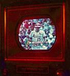
I have made some progress. I have a good raster. I may even have video, since there is snow on the screen. No sound at all. The audio detector gets B+ from the boost line. I need to verify voltage on the sound board. Then I'll connect the TV Analyzer to the antenna terminals and try to adjust the fine tuning. I got the raster going late this afternoon and didn't have time to go any further. I can change channels and get a flash on the screen. Is this an indication that the tuner is working, and my problem is in the IF/audio sections? I appreciate everyone's help on this.
|
|
#28
01-05-2024, 04:33 PM
|
|||
|
|||
|
I have a raster, I have an image when I inject a signal into the antenna terminals with the 1077B Analyzer. The vertical height is off, probably linearity as well and the horizontal may be too fat. I think I can say the tuner is okay. I still have no sound. I have run continuity tests on the sound board and can't find anything open. I have B+ on the audio detector tube and the other voltages are okay. I have correct voltage on the 6GC5 cathode follower tube. I have correct voltages on the audio IF tube as well. I'm not having any success feeding an audio signal from the Analyzer to the sound IF. I'm not sure how to troubleshoot the audio section. There is a quaduature coil. I'm not sure what it does or how to test it. I haven't connected a DVD player to it yet, but the image from the Analyzer looks good as far as focus and contrast is concerned. I had to play with the fine tuning to get it close enough to get an image. If I could figure out why I have no sound, this project might be successful yet. Thanks for any advice you can give...
|
|
#29
01-05-2024, 06:20 PM
|
|||
|
|||
|
Finding all the voltages on the sound board to be correct, I decided to examine the drawing and check component by component, every component in the audio stream. I noticed a notation on the drawing that said "Mute connection (where used)". Hmmmm. This stereo has remote control. It turns power off and on, changes volume in three steps, and changes the TV channels in one direction only. Apparently, it has a muting feature so the movement of the tuner is not heard in the audio (good old Magnavox!). Apparently, that switch had shorted, killing the audio. I disconnected the RCA plug on the end of that wire and the audio came to life. I have adjustments to make, I have no idea what high voltage I have, no idea of cathode current, vertical is off, horizontal may be off a bit, too. This thing allegedly has "automatic fine tuning" so changing the fine tuning with the knob is made purposely difficult. I'll remove the channel knob to get to the fine tuning knob better to adjust it. I've made progress and am satisfied with the outcome so far. And, I've learned a lot.
|
|
#30
01-05-2024, 08:13 PM
|
||||
|
||||
|
The muting feature is a leaf switch on the back of the channel motor. When the motor is activated, the motor shaft goes into the gear box and the switch closes, when the motor stops, the spring loaded shaft pops back out and opens the switch. The automatic fine tuning was what everyone else called pre-set fine tuning. Each channel tuned individually, adjusting any one channel didn't affect the others.
Last edited by damen; 01-05-2024 at 08:18 PM. Reason: fine tuning
|
| Audiokarma |
 |
|
|


 Linear Mode

