
|
|
|
#46
 05-14-2011, 04:52 PM
|
||||
|
||||
|
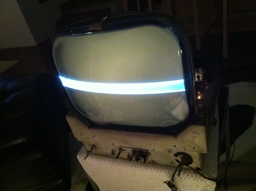
It might be a while until I get my hands on the correct transformer so I was thinking about working on another problem I have with the set. The picture above was taken from a side angle so it's not as obvious as when you look straight on at it, but the picture is skewed to the right and not level. Can any one point me in the right direction towards a fix for that? Is that something that I can work on now, or should I wait until I have the transformer and a full height picture?
I found another Majestic on Craigslist in my area with the same deflection problem...I wonder if that is a common thing with these sets. http://pittsburgh.craigslist.org/atq/2380646109.html Last edited by vts1134; 05-14-2011 at 05:03 PM. 
|
|
#47
05-14-2011, 06:09 PM
|
||||
|
||||
|
I'd hold off until you have a new transformer. I've seen a few other threads here where people had no vertical, and the line often looked a bit skewed.
Once you have an actual picture, you can then display a test pattern/grid to aid in adjustments, and do all of the convergence/purity stuff in one swoop. If memory serves, you can "rotate" the picture by rotating the entire convergence assembly , as that will adjust the directions that the magnetic field deflects the beams. There are usually a set of rubber wedges under the yoke to keep it from moving. You should mark their positions before you remove them, otherwise your centering will be off when you reassemble. Here's an interesting read while you wait. This discusses purity adjustments on newer colour CRTs, but the principles behind it still hold. http://personalpages.tds.net/~rcarlsen/cbm/converge.txt
|
|
#50
05-16-2011, 03:10 PM
|
||||
|
||||
|
Should do the job. The turns ratio that is key to the magic that makes it work.
The only thing you may run into is the polarity (I suppose "phasing" is a better term since we're dealing with AC) - if it doesn't work, reverse the leads to one of the two sides and try again. I don't know what would happen if you got the phasing out of sync here - If it's part of an oscillator, then it probably wouldn't oscillate, but since it's part of the vertical section, you might also end up with an upside-down picture  (either way, it's a "safe" mistake - things won't go bang if it's wrong) (either way, it's a "safe" mistake - things won't go bang if it's wrong)
|
| Audiokarma |
|
#51
05-17-2011, 12:46 AM
|
||||
|
||||
|
Vintagepc, I believe that this is not a color TV so it should not have purity or convergence adjustments.
|
|
#52
05-17-2011, 05:58 AM
|
||||
|
||||
|
Quote:

|
|
#53
05-17-2011, 10:34 AM
|
|||
|
|||
|
Quote:
 oc(Bill) oc(Bill)
|
|
#54
05-17-2011, 08:24 PM
|
||||
|
||||
|
Got the new transformer in the set and it gives deflection but not a full picture. It did bring the horizontal picture back to the center again. Even though it was not a full height picture it did for the first time look "correct." It might be because I could see scan lines for the first time, or because the picture was horizontally aligned, or it could just all be in my head. I did try adjusting the vertical hold control, the vertical linearity control, and the vertical size control, all to no avail. The transformer I used was a Stancor model a-8122. The turn ratio was 1:4.2. The primary and secondary impedance was a bit different on the replacement than the schematics showed on the original. The original was 160 and 1,300 and the replacement was 170 and 940. Could the transformer still be the problem or is it time to look elsewhere?
|
|
#55
05-18-2011, 06:22 AM
|
||||
|
||||
|
Do the vertical controls do absolutely nothing to change the bar, or just that they don't get it to a proper height?
You don't mention it, but I assume you tried the lead swap on one of the transformer windings to check if the phasing was right? If you did, it's probably time to start looking elsewhere; you've got "partial" vertical, as opposed to flat-out no vertical. That would suggest an out-of-spec component - time to start ohming out the resistors in, and before, the vertical section to see if any have gone high if you haven't already done so. If those all check out fine, then it can shift the focus back to the transformer; less of a headache that way than trying to source an exact match and finding it still doesn't work. Are you able to borrow or access an oscilloscope? Those can come in handy when trying to figure out the problem, since the actual shape and tracing back of the waveforms can point to the cause relatively quickly (i.e. if the problem is caused by the vertical section, or the result of something before) ... but it can be done without.
|
| Audiokarma |
|
#56
05-18-2011, 09:18 AM
|
||||
|
||||
|
Honestly I hadn't tried swapping the leads on the transformer. I guess my assumption was that if I wired it incorrectly that I would have no deflection at all. I'll try that first tonight. Thank you for taking the time to point out the painfully obvious, sometimes(hopefully THIS time) it helps.
|
|
#57
05-18-2011, 02:30 PM
|
||||
|
||||
|
Quote:
|
|
#58
05-18-2011, 04:24 PM
|
||||
|
||||
|
Switched the leads on the secondary of the transformer and it had little effect. The vertical was the same size. The only difference was the image was again shifted to the right of the screen. I switched the leads back and the image was centered. I did take v13 to a shop to test it and it passed, although the guy admitted that he hadn't used his tester in quite some time so it may have been way out of calibration. There is another shop in town that I know I can trust if I take the tube there to test it so I may do that. He may be able to give some advice if it passes, and sell me another one if it fails. If every thing checks out there it's time to move on.
I do have access to a scope btw so if there is some tests I can run with it to narrow my search down before I start checking every capacitor and resistor that would be fantastic.
|
|
#59
05-18-2011, 05:13 PM
|
||||
|
||||
|
It would have been too good to be true if it had worked
I don't have a scope myself, but often the service manuals (Sams or otherwise) will have diagrams showing what the waveform should look like at various test points in the set. If you don't have that, then perhaps someone more familiar with the waveforms that should be there can point you in the right direction for where to test and what it should look like. If the v. controls do absolutely nothing, then I'd check those as well before going resistor-hunting... Sometimes dirty pots can cause weird problems.
|
|
#60
05-18-2011, 05:19 PM
|
||||
|
||||
|
Your Sams doesn't include model waveforms for the vertical circuits, unfortunately.
It does include a voltage chart. You can use a voltmeter to check voltages on V13 and V14 and then compare them to the voltages given in the chart. If you find one that's way off, you can then check the components in that neighborhood. Put one hand in your pocket when touching the voltmeter probe to anything on the live chassis. Also double-check your previous work, making sure that you (or a previous handyman) didn't miswire a replacement capacitor, drop a blob of solder somewhere, or accidentally nudge some component so that it creates a short circuit. Even experienced restorers slip up every once in a while. Phil Nelson
|
| Audiokarma |
 |
| Thread Tools | |
| Display Modes | |
|
|


 Linear Mode

