
|
|
|
#46
 01-29-2012, 06:37 AM
|
||||
|
||||
|
Quote:
") . I'm sure it wont be the last time I run into that in my life and as I get better I'll be able to spot those mistakes before I make them. Had I analyzed the schematic and thought about where that capacitor was going/what it was doing instead of just going on faith I probably would have known it to be incorrect. . I'm sure it wont be the last time I run into that in my life and as I get better I'll be able to spot those mistakes before I make them. Had I analyzed the schematic and thought about where that capacitor was going/what it was doing instead of just going on faith I probably would have known it to be incorrect.

|
|
#47
01-29-2012, 12:17 PM
|
||||
|
||||
|
On multi-section cans I tend to check with the labeling of the can and the existant wiring to make sure of my work.
The first time I made that sort mistake I blew two lytics in a row because I could not find a way to get the chassis loose (the mounting nuts were recessed out of reach of a wrench), and a rubber AC mains line had disintegrated and shorted to one of the above chassis lytics. The second time was a TV that I'd miss wired the replacements for the selenium doubler rectifiers on.....I was powering it up on a variac, went to have dinner, and started hearing a regular popping sound as the two sets of 5 22uF caps I had put in parallel to make up a replacement for each doubler cap started firing their guts out one by one.
__________________
Tom C. Zenith: The quality stays in EVEN after the name falls off! What I want. --> http://www.videokarma.org/showpost.p...62&postcount=4
|
|
#48
01-29-2012, 01:40 PM
|
||||
|
||||
|
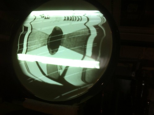
Well I have run into my first stumper. I'm having a problem with the vertical. There's a short video of the problem in the link below (the set is on it's side btw).
http://www.youtube.com/watch?v=WXtdZeuZpO8 I've gone through the resistors in the vertical section and they all read within 20% of spec. I've also swapped the 6SN7 out. The problem kind of looks like the oscillator is running too slowly but the dual "rolling" lines have me stumped. Any one got any ideas?
|
|
#49
01-29-2012, 03:08 PM
|
|||
|
|||
|
What does it look like with a regular picture?
|
|
#50
01-29-2012, 03:18 PM
|
||||
|
||||
|
Looks like the vertical is not locked, and it's got a sine wave rolling through it. Scope the sync section, see if you can catch the sine wave. Could be a heater/cathode leak or short.
__________________
Evolution... 
|
| Audiokarma |
|
#51
01-29-2012, 04:52 PM
|
||||
|
||||
|
Quote:
|
|
#52
01-29-2012, 05:05 PM
|
|||
|
|||
|
If you adjust the vert hold control, will it lock to the hum bar? Or does the bar still "roll" irrespective of the v hold setting?
|
|
#53
01-29-2012, 05:53 PM
|
||||
|
||||
|
It's tough to explain, when I adjust the vert hold it will start to roll the way sets normally do when you are out of vertical lock. Then I can get it to "lock" on the horizontal bar but it still rolls slowly in the way that you can see in the video. One thing I noticed is that the voltage on the grid of the vertical output (pin 4) moves up and down 5-6 volts in tune with the rolling bars.
|
|
#54
01-29-2012, 06:04 PM
|
|||
|
|||
|
Sounds like a heavy power supply ripple is getting into the vert circuit. Possibly one of the filters is miswired(?).
|
|
#56
01-29-2012, 06:41 PM
|
||||
|
||||
|
The video reminds me of when my 1953 Zenith had it's vertical working at double frequency.
Have you made sure all resistors in the vertical are in tolerance? Those can really louse things up if they have drifted too far off value.
__________________
Tom C. Zenith: The quality stays in EVEN after the name falls off! What I want. --> http://www.videokarma.org/showpost.p...62&postcount=4
|
|
#57
01-29-2012, 06:55 PM
|
||||
|
||||
|
Quote:
|
|
#58
02-05-2012, 12:19 PM
|
||||
|
||||
|
Quote:
 . .Quote:
 Any thoughts?
|
|
#60
02-05-2012, 02:47 PM
|
|||
|
|||
|
Quote:
If you've got an extra 'lytic cap of equivalent rating as the main filters, you can jumper each one and see if the ripple disappears. Or alternately if you have an analog AC voltmeter, you can measure ripple. Just put a cap of .1mf or so in series with the meter's hot lead (to block the DC component). I'm not sure i would trust a digital meter in that application.
|
| Audiokarma |
 |
|
|


 Linear Mode

