
|
|
|
#31
 11-11-2013, 08:42 PM
|
||||
|
||||
|
Thanks. I figure I should replace both sections while I'm at it. I think 1500 and 2200 should be close enough to the original 1480 and 2140.
I managed to get the yoke and FC off so I can try it out on the workbench with a test CRT. There's clearly a weld where it was rebuilt and the yoke was reluctant to slide over that portion of the neck. Some slow careful rotating back and forth did the trick. 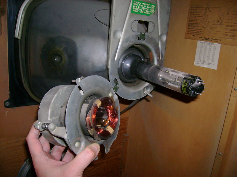

|
|
#32
11-12-2013, 07:57 AM
|
||||
|
||||
|
Good, I'm glad you were able to get the yoke off. I'm not going to mess with mine until the 17AP4 gets tired, which will probably be years from now.
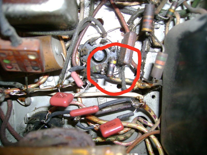
BTW, that 25K resistor in the horizontal output was toast on mine, too. I also initially mistook it for a paper cap. Looking forward to seeing you fire it up on the bench with a test CRT! -Clark
|
|
#33
11-12-2013, 09:42 AM
|
|||
|
|||
|
Quote:
I see some Allen-Bradley five percent resistors used. 
|
|
#34
11-12-2013, 12:27 PM
|
||||
|
||||
|
OK, I'll put a good 47 in there. Are you referring to the 5% resistors in the upper-right ? I guess Dumont used better quality parts than their competitors. I'm finding very few that need replacing

|
|
#35
11-12-2013, 01:01 PM
|
|||
|
|||
|
Quote:
The German resistors had the flat leads. I read somewhere that there was a parts shortage during the Korean war.
|
| Audiokarma |
|
#36
11-13-2013, 12:37 AM
|
||||
|
||||
|
I've worked on a couple early 50s Admirals with resistors like that.
I took a closer look at the anode lead and discovered two splices with a piece of line cord between and the rubber cap is falling apart! That's all going to be replaced  
|
|
#37
11-13-2013, 04:49 AM
|
||||
|
||||
|
Quote:
Back in the day, before air-conditioning, we used to see a lot of this from shade tree mechanics who tried to stop arcing on the anode connector due to high humidity. Usually, it took a razor blade to scrape off the mess and doing that destroyed the connector in the process. Jas.
|
|
#38
11-13-2013, 11:02 AM
|
||||
|
||||
|
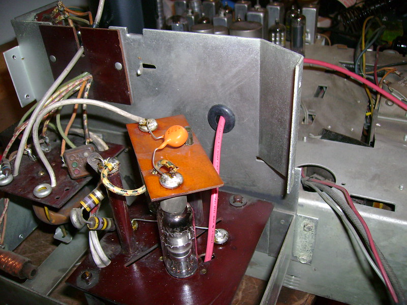
I dove inside the HV box last night and found more evidence of old repairs.
All three HV caps had been replaced. They used "pigtails" with pointy leads sticking out rather than plunging the ends into the solder cups. Not the proper way to dress HV connections  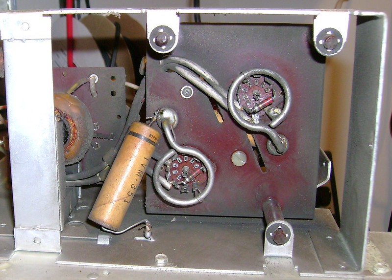 One of the 2.2 ohm filament resistors had cracked so I replaced them both. 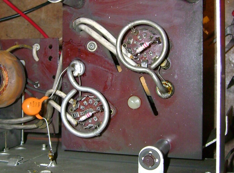 More evidence of past HV troubles. I think this Micamold cap is 0.001 mfd @ 500v and the white dot indicates it's really paper inside so I'm going to replace it. 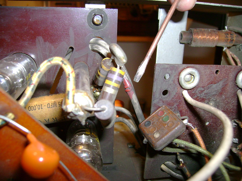
|
|
#39
11-13-2013, 12:23 PM
|
||||
|
||||
|
Quote:
I also chose not to pigtail the HV caps. Getting the solder to pool just right in the cups was a bit of challenge, though. I found it best to orient the chassis so that the solder cup I was working on was horizontal, otherwise gravity causes too much of the solder to spill out. Looks like you're getting close to the first power-up.
|
|
#40
11-13-2013, 12:47 PM
|
||||
|
||||
|
Quote:
Quote:
|
| Audiokarma |
|
#41
11-14-2013, 11:50 PM
|
||||
|
||||
|
The Dumont service info lists that cap as a mica so I'll leave it alone after all.
|
|
#42
11-16-2013, 07:57 PM
|
||||
|
||||
|
I finished up work inside the HV box including a new 40kV anode lead.
 United Electron 1X2 tubes. I don't think I've seen this brand before 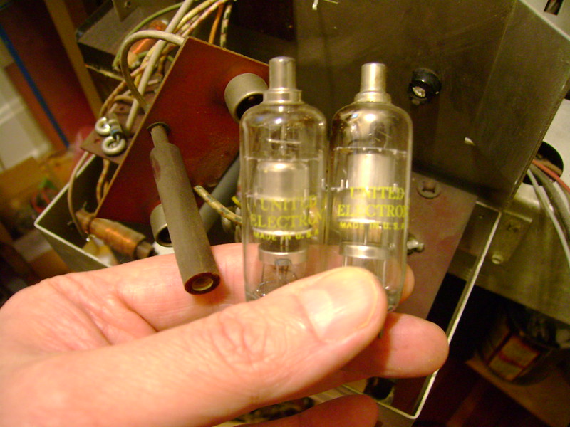
|
|
#43
11-16-2013, 08:16 PM
|
|||
|
|||
|
Here's a link to AK that'll probably tell you more than you ever wanted to know about United Electron tubes. Sounds like they were one of those dime store brands.
http://www.audiokarma.org/forums/sho...d.php?t=179305 What size and type of wire did you use for the anode lead?
|
|
#44
11-16-2013, 09:50 PM
|
||||
|
||||
|
Thanks for the link. 20 AWG 40kV wire salvaged from a more modern TV
|
|
#45
11-17-2013, 08:41 PM
|
||||
|
||||
|
I salvaged a nice anode cap from an Admiral then continued work under the chassis.
 Better take a look inside this box.  Yep, two more paper caps and some resistors almost double the resistance they should be. 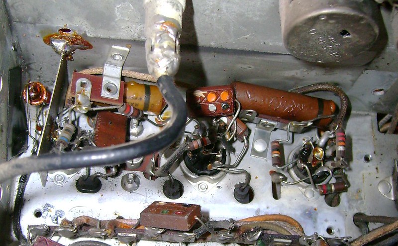
|
| Audiokarma |
 |
|
|


 Linear Mode

