
|
|
|
#1
 05-19-2016, 02:30 PM
|
||||
|
||||
|
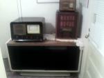
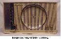
Mystery chassis....??
Got this chassis as a present from DavGoodlin
 He said it was an Admiral, but there's no way it's an Admiral. Take a gander and see what you think it is...... The only indication is a mark of Emerson on the ballast tube, but I can't find any Emerson sets that have this style control layout. Look at all the filter cans!!!  And a ballast tube and selenium rectifiers with a 12" screen. This is an odd duck, whatever it is..... And a ballast tube and selenium rectifiers with a 12" screen. This is an odd duck, whatever it is.....
__________________
"Restoring a tube TV is like going to war. A color one is like a land war in Asia." 
|
|
#4
05-19-2016, 03:00 PM
|
||||
|
||||
|
I have never seen the 12" model but this chassis likely came out of a combo like the 618 or 630.
http://ebid.s3.amazonaws.com/upload_...7-16520-24.jpg edit add: earlier thread about a 10" model found in Denver: http://www.videokarma.org/showthread.php?t=266947 jr Last edited by jr_tech; 05-19-2016 at 03:10 PM. Reason: add link
|
|
#5
05-19-2016, 03:32 PM
|
||||
|
||||
|
Could be an Emerson 571B, the 571A had the 25Z6 nightmare, the 571B had Seleniums IIRC.
Definitely Emerson though. In any case it's an awful set to recap, just look at all those cans! Edit, you said it has a 12" tube so not a 571. 
|
| Audiokarma |
|
#6
05-19-2016, 05:25 PM
|
||||
|
||||
|
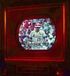
Well, either way.....it's getting stripped and hitting the curb unless someone needs parts off'n it. Testing the 12LP4, so we'll hope for the best there
__________________
"Restoring a tube TV is like going to war. A color one is like a land war in Asia."
|
|
#7
05-19-2016, 06:56 PM
|
||||
|
||||
|
I recently "did" an Emerson 698 14 inch from 1951, and it was a real PIA. One of the only things that saved it from being parted out was that the 14BP4 has excellent emission, and also it is a very clean set, inside and out. And it's small. The power supply circuitry is a nightmare, and I wonder about the EE's who designed it. Still has some fold over issues, but I'm done with it for now. Decent pic though, aside from the minor deflection issue.
 Kevin
__________________
stromberg6
|
|
#9
05-19-2016, 07:21 PM
|
||||
|
||||
|
I wondered back in 1980 or so...ans STILL do wonder today--seeing that picture again..why did they use SO MANY filter cans? Reminds me of the "locomotive chassis" that has a lot of caps --I think the 1st gen or so.. I understand the ened for a few caps for a doubler and filtering--but beyond that?
|
|
#10
05-19-2016, 07:55 PM
|
||||
|
||||
|
Quote:
http://www.earlytelevision.org/pdf/E...Sams-76-11.pdf jr
|
| Audiokarma |
|
#11
05-19-2016, 08:34 PM
|
||||
|
||||
|
Quote:
I don't know where you saw that Emerson logo. I looked at the ballast tube and didn't see anything but a perforated cylinder over the tube itself; there was no logo on that cylinder, unless I was looking at the wrong part. BTW, this is the first TV I've ever seen that uses a ballast tube in the power supply. Every set I've ever worked on has had a power transformer and at least one 5U4 rectifier, or series string filaments with seleniums. That this set uses a ballast tube probably dates it to the late 1940s--'47 or '48. By 1950, however, I am sure the 5U4 had taken hold as the rectifier tube of choice in most TVs, although my folks' second set, a 1955 Crosley Super V 21" b&w console, still used selenium B+ rectifiers. That set had two such rectifiers, probably wired in parallel across the output of the B+ supply. The plate voltage for the tubes was probably taken directly from the output of the rectifiers and fed through at least one filter capacitor.
__________________
Jeff, WB8NHV Collecting, restoring and enjoying vintage Zenith radios since 2002 Zenith. Gone, but not forgotten.
|
|
#13
05-19-2016, 09:57 PM
|
||||
|
||||
|
Quote:
jr Last edited by jr_tech; 05-19-2016 at 10:01 PM.
|
|
#14
05-19-2016, 10:00 PM
|
|||
|
|||
|
Quote:
The first set, my parents bought was the TV only model, using that type chassis. A smaller type console, where the speaker was as large as the picture. The ballast was for surge limiting of the two power supplies. The CRT went weak, when the set was about four years old. They gave it to me, to take it apart when I was about ten years old. Regarding the Crosley set, that model used a voltage doubler, two seleniums and a voltage doubling cap, before the two rectifiers and two caps and a choke to furnish the B+ voltages. It also used the audio output tube as a voltage divider. I common scheme that many manufacturers used. 
|
|
#15
05-19-2016, 10:21 PM
|
||||
|
||||
|
Quote:
|
| Audiokarma |
 |
| Thread Tools | |
| Display Modes | |
|
|


 Linear Mode

