
|
|
|
#136
 04-06-2015, 02:13 AM
|
||||
|
||||
|
Thanks, I have tried injecting a video signal (color bars) at the input of the first video amp, without getting a coherent color image. I believe the TV expects a signal of about 2.7 volts there, but my generator can supply only 1.5 volts at most, so perhaps the signal is just too weak.
The RCA manual ( http://antiqueradio.org/art/RCA%20CT...e%20Manual.pdf ) has an interesting section on pages 22-23, "AFC alignment used for chrominance circuit analysis." It explains how to remove the chroma bandpass tube and then measure voltages at the chroma phase detector, R-Y/G-Y demodulators, and 3.58-mc oscillator, to determine whether the 3.58-mc signal is present and traveling where it's supposed to go. My set flunked all of those tests, so I am starting to wonder if it has more than one problem (wouldn't be the first time). For instance, maybe it has lousy video alignment AND the chroma reference oscillator is not running (or running at the wrong frequency). I thought I had licked the IF socket problem. I gave all three sockets yet another military-grade cleaning and then resoldered the 3rd IF socket pins. This seemed to eliminate the intermittency, but after messing with various things for a couple of hours, the problem returned. Tomorrow I'm going to complete the systematic voltage & resistance checks which I started a long time ago and never finished. Phil Nelson 
|
|
#137
04-06-2015, 09:20 AM
|
||||
|
||||
|
Might be time for new sockets. IIRC surplus sales of Nebraska had the correct sockets for these last time I checked (a good 3 years ago). I've been wanting to buy three new Video IF sockets for my CTC-4, but have yet to come up with a minimum order to merit purchasing them, and like you I've got alignment issues and lack the knowledge/equipment/time to do pick up the craft......After I graduate this year I hope to have sufficient free time and monies to gear up for TV alignment.
__________________
Tom C. Zenith: The quality stays in EVEN after the name falls off! What I want. --> http://www.videokarma.org/showpost.p...62&postcount=4
|
|
#138
04-06-2015, 01:34 PM
|
||||
|
||||
|
To give direct video input another shot, I disconnected the output from the video detector to the 1st video amp, and injected a video signal to the video amp grid. I started with a B/W crosshatch pattern so that I could adjust the screen background, etc., to make a normal display.
 Then I switched to a color bar pattern. 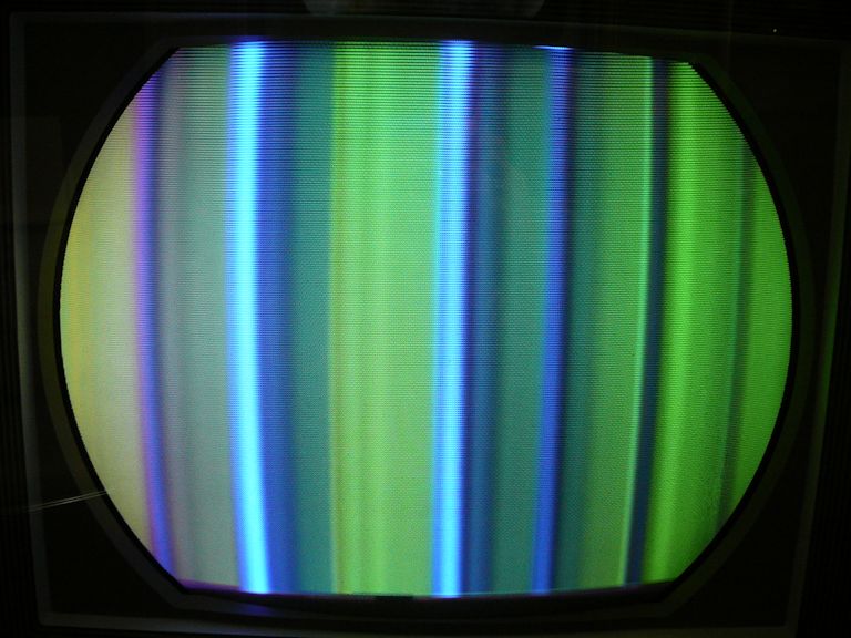 Adjusting the Color control, etc., gives nothing like a normal color-bar progression, so I'll check out the color circuits. Phil Nelson
|
|
#139
04-06-2015, 01:43 PM
|
||||
|
||||
|
That would appear to be a symptom of the chroma reference osc. not working properly.
__________________
Tom C. Zenith: The quality stays in EVEN after the name falls off! What I want. --> http://www.videokarma.org/showpost.p...62&postcount=4
|
|
#140
04-06-2015, 03:00 PM
|
||||
|
||||
|
Yes, that will be my first stop. The previous tests gave no evidence of the chroma oscillator working, and I just ran across this note in another part of the manual:
"If the 3.58 mc. subcarrier oscillator does not operate and provide adequate bias voltage to the grids of the G-Y and R-Y demodulators, a picture having an overall yellow-green cast will result." That just about describes that awful color-bar image. I don't know if you can test a crystal with my feeble collection of instruments, but I have a handful of 3.58-mc crystals left over from previous adventures, so I can test by substitution if I have reason to suspect a bum crystal. Phil Nelson
|
| Audiokarma |
|
#141
04-06-2015, 09:06 PM
|
||||
|
||||
|
Why not just poke around in the chroma
of area with your scope? See if the oscillator is oscillating. If so, then ... Look for a burst at the output of the burst keyer. Do note that the color won't sync unless the horizontal is working correctly. I don't know if the color killer will kill the color if the horizontal pulse driving it is not right. It doesn't on my CT-100. It seems that you already have scoped for seeing color subcarrier somewhere in the video, and not seeing it. But was the horizontal output tube replaced by then? If not ... expect problems because the AGC won't work without it. On my CT-100 the IF response becomes hopelessly narrow and peaked in the middle of the channel.
|
|
#142
04-07-2015, 01:18 AM
|
||||
|
||||
|
Thanks, I replaced the horizontal output tube right after I fixed the horiz oscillator.
Earlier today I started scoping things in the chroma circuits. Since it's doubtful whether the IF section is passing a color signal, I disconnected the output from the video detector and injected a video signal from the pattern generator at the video amp grid. With luck, I can get some clue whether the chroma circuits are operating. The waveforms on the burst keyer tube look pretty normal. Here's the burst keyer grid (pin 9):  Here's the burst keyer plate (pin 1):  Here's the burst keyer cathode (pin 8):   I also scoped the bandpass amplifier, demodulator driver, color killer, blanking amp, and G-Y/R-Y demodulator: http://antiqueradio.org/art/temp/RCA...ndpassGrid.jpg http://antiqueradio.org/art/temp/RCA...DriverGrid.jpg http://antiqueradio.org/art/temp/RCA...KillerGrid.jpg http://antiqueradio.org/art/temp/RCA...ingAmpGrid.jpg http://antiqueradio.org/art/temp/RCA...ulatorGrid.jpg http://antiqueradio.org/art/temp/RCA...atorOutput.jpg http://antiqueradio.org/art/temp/RCA...ulatorGrid.jpg I haven't pored over all this yet, but I get the idea that some of those circuits are operating, anyhow. Phil Nelson
|
|
#143
04-07-2015, 10:06 AM
|
|||
|
|||
|
Phil,
Although I'm not overly familiar with sets earller than CTC-12, I'm assuming the following 'quick & dirty' check is valid for your CTC-4 as well: While watching the colorbar display as shown in your post# 138, rotate the color control thru its full range, from zero to maximum, a few times. Does that greenish component vary in intensity, extinguishing completely at the zero setting? If so, it indicates the chroma signal amplitude is being displayed, but without the local phase reference signal. In other words, the 3.58 oscillator is not running.
|
|
#144
04-07-2015, 11:46 AM
|
||||
|
||||
|
Or not running at the correct frequency. The procedure for aligning the local oscillator is to ground the input to the reactance tube, then twiddle the slug of the oscillator till color bars slowly float by. If it won't even do that, it's not running and you can verify by loosely coupling a scope probe to the 3.58 tube's plate and look for a sine wave output.
__________________
Evolution... 
|
|
#145
04-07-2015, 01:44 PM
|
||||
|
||||
|
I suspect the oscillator is simply not running. Trying old_coot88's test, when I turn down the color control, the color in the color bar pattern is totally extinguished.
When I check voltages on that tube (V124A, 6AZ8), the grid at pin 6 shows 0V instead of the expected -10V. I see no waveform at all when I put the scope probe at (or near) the plate, pin 1, as miniman82 suggested.  The other voltages at that tube are in the right ballpark and the resistance at pin 6 is correct (47K). I guess the obvious question is, why no negative voltage at pin 6? The other check, watching for drifting color bars while you move the oscillator slug, is part of the color AFC alignment procedure that I mentioned earlier.  When I made this check, no drifting bars were visible, leading to the conclusion that the free running frequency of the oscillator is not correct. Phil Nelson
|
| Audiokarma |
|
#146
04-07-2015, 02:21 PM
|
|||
|
|||
|
Did you check the reactance coil itself for continuity, and +280V on the plate of the reactance tube?
(open reactance coils were pretty common on CTC-15 forward, dunno about CTC-4s.)
|
|
#147
04-07-2015, 02:50 PM
|
||||
|
||||
|
I measured about +270V on the plate (pin 6) of the reactance tube (V122B). The reactance coil L127 has continuity, measuring about 10 ohms resistance.
Phil Nelson
|
|
#148
04-07-2015, 02:56 PM
|
|||
|
|||
|
How about plate and screen grid voltages on the osc. tube? And continuity of the coil going to the cathode? If all good, maybe the xtal.
|
|
#149
04-07-2015, 03:10 PM
|
||||
|
||||
|
I measure +249V on pin 1 and +118V on pin 2 of V124A. Resistance from pin 3 to ground is zero, suggesting that coil L42 has continuity. Maybe I will dig out one of those spare crystals and try substituting it. They are all the plug-in type, so I'll need to solder on some little leads.
Phil Nelson
|
 |
|
|


 Linear Mode

