
|
|
|
|
|
#1
 11-09-2017, 12:35 AM
|
||||
|
||||
|
For grins, I took the cover off of the VHF tuner... YIKES! brain surgery is correct! Here is what mine looks like:
 I have identified the 4 varactor tuning diodes and painted the tops with red paint... the 5 band switching PIN diodes were factory painted yellow (#5 is barely visible under coil next to blue and red top semiconductors)... the RF transistor (barely visible under tan wire and coil) was factory painted white and the oscillator and mixer transistors are painted blue on the tops. Do we agree? jr 
|
|
#2
11-09-2017, 04:56 AM
|
||||
|
||||
|
Quote:
Last edited by timmy; 11-09-2017 at 05:22 AM.
|
|
#3
11-09-2017, 05:45 PM
|
||||
|
||||
|
Can anyone identify this part?
This is what I believe is one of the varactor tuning diodes in the Sinclair MTV-1 VHF tuner section (pictured above)... it is in a TO-92 style case with no markings on the flat side, just 3 color bands on the back. (I painted the red on the top for identification in my previous post)
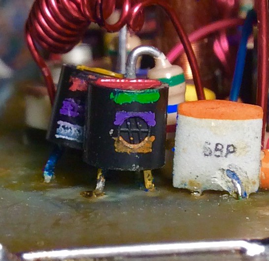 Apparently the tuning voltage in the set can go as high as 31 volts. Identification and/or substitution recommendations needed. Thanks, jr .
|
|
#4
11-09-2017, 06:08 PM
|
||||
|
||||
|
Quote:
|
|
#5
11-10-2017, 01:42 PM
|
||||
|
||||
|
Quote:
jr
|
| Audiokarma |
|
#6
11-10-2017, 03:00 PM
|
||||
|
||||
|
I have 3 volts on pin 7 but the hv just bearly gets of the start line of the hv probe. Actually aside from a dark screen the pic was still visible so maybe it's the hv I knocked out.
Last edited by timmy; 11-10-2017 at 03:05 PM.
|
|
#7
11-10-2017, 06:00 PM
|
||||
|
||||
|
Grasping at straws, I would check/replace the 3 electrolytic cans between the ic and the HV transformer... the surge might have injured them... the diode standing up between two of the cans could be suspect as well as the 4 transistors in the area. A very real possibility is that the regulator circuit on the ic has been damaged. I really can't guess.
jr
|
 |
|
|


 Hybrid Mode
