
|
|
|
#1
 06-10-2016, 03:56 PM
|
||||
|
||||
|
CRV59-AAE Military Iconoscope Camera restoration
I am beginning the restoration process on the CRV59-AAE Military Iconoscope Camera (and spare Iconoscope) that I bought at the May RTF meeting.
Some time ago I ordered uo from Mouser the needed list of parts. The only odd ones are for the power supply. First is the power transformer for the +405 and -50 volt supplies, which is a Hammond 290EX Guitar Amp transformer. It has the requisite 50 volt (RMS) tap for the -50v. The +27 volt filament and bias supply is a Meanwell LRF-150F-24 switching supply to which I intend to add a bit of switching crap filtration. Last night I had again inspected the chassis, tried to remove the bad-looking iconoscope, and tried following wires and testing pots. I could not get the iconosocpe out. It looked like the yoke was set to make that impossible without removing pots. Today I bought new batteries for my flashlight and inspected better: yes, there is an adjustment and if moved a bit the tube comes out safely. All the stuff I tested looks OK especially the low-ohm pots I was able to test in-circuit. Except that the bias lamp appears missing entirely, no lamp, no wire, no socket. Huh??? The shutter was removed previously. With the old iconoscope out I was able to test it in a tube tester for emission and gas (transconductance too, but that's expected to be very very low). I had previously tested the new one, and it looked OK. The old one is clearly very very gassy, and a retest of the new one under identical settings shows no gas. There is hope! Next up is lots and lots of photos and more circuit tracing. Has anyone else around here other than McVoy had any experience with one of these? Doug McDonald 
|
|
#2
06-12-2016, 05:54 PM
|
||||
|
||||
|
I have now replaced all the 450 volt (B+) electrolytics, C127, C142, C101, C126.
The first two are cans in the main part and were restuffed. C101 was not resutuffed because the tabs were too stiff to twist into removal position. C126 was not resutffed out of "symmetry" with C101, and there's a nice spot for it. The two 0.05 uF caps in the preamp area were replaced with modern ones (C113 and C114). I have not decided whether to replace the LV (15 volt) electrolytics, C147 and C115. C115 would be easy, C147 even more impossible than C101, to restuff, so if they are bad they will just have their wires cut and the replacements tacked in. These caps are usually OK.
|
|
#3
06-13-2016, 10:38 PM
|
||||
|
||||
|
All the tubular paper caps are now replaced.
Next up is disconnecting the 6X5 plate and catghode and replacing with 1600PIV silicon diodes. Then I will test the +28 and -50 volt resistor chains using the 28 volt supply, and the +400 (no filament power) using a lab supply.
|
|
#4
06-14-2016, 12:22 PM
|
||||
|
||||
|
It turns out that the modifications mentioned in the ham radio article,
to use AC on the filaments, were done at some point, and will have to be undone (very easy, but its good we have a local source for ordinary resistors and a few caps.).
|
|
#5
06-14-2016, 09:39 PM
|
||||
|
||||
|
The circuit changes in the +28 volt area were undone, not physically easy, as big
wires were twisted on tightly. The 6x5s (except heaters) were removed from the circuit and replaced with 1800V PIV silicon diodes, these being specifically specified for damper and CRT supply use. The +28 and minus 50 circuits were checked out using the 28v supply and appear to work OK. Next is build the power supply.
|
| Audiokarma |
|
#6
06-16-2016, 09:32 PM
|
||||
|
||||
|
The 405 volt supply is built and tested. It was applied to the set
and immediately showed that R210, the 1000 resistor that feeds the gas regulator tubes, was open, These are still available. I was able to temporarily replace it with 200 ohm resistors in series. This showed that at least most of the B+ chain is working OK. Next up is the -50 volt supply, the noise filter for the 28 volt supply, and the power cable.
|
|
#7
06-17-2016, 09:23 PM
|
||||
|
||||
|
The power supply is complete and connected.
The electronics, without the iconoscope, was turn completely on. All the various sections work. The vertical frequency adjust is out of range, it wont reach as high as 40Hz. This would not matter if I were forcing it to 60Hz, but I've not done that yet. My soldering iron died and the old 250 watt gun is too clumsy, so I'm out of doing changes until I can borrow one from a colleague's lab.
|
|
#8
06-18-2016, 08:49 PM
|
||||
|
||||
|
I got a new iron.
I got the vertical in range. As designed it is NOT random interlace! It in fact is roughly (now) 260 x 60p. But at these extended frequencies (originally it was about 300 x 40p) the stability is marginal. I will continue testing before installing the iconoscope.
|
|
#10
06-19-2016, 06:03 PM
|
||||
|
||||
|
I have a very complete set of "before" pictures. I'm rather tired out this evening, so its
unsafe to do more work. I'll try to take the "after" pictures and ones of the power supply, which still lacks the sync modifier suggested bu McVoy. Today was devoted to troubleshooting (electronic tests only ... the first iconoscope test will be tomorrow). The power to the iconoscope filament was inadequate. It took quite a while to prove this, as I have no AC voltmeter that works at 16 kHz. I had to use an analog scope or compare filament brightness between two identical tubes, one on the camera and one on 6.3vac. Tomorrow I'll bring a digital scope that can do true RMS AC. The problem was that the screen resistor, supposed to be 82K, was 106K. This caused the screen voltage to drop to zero at high power, thus limiting. Even 82K did not work, I eventually used 60K. Then I worked more on the video amplifier chain. It was horrendously microphonic, as if there were a broken lead connection. There was., onC154, a 1000pF mica in series with a 0.05 uF film cap (??? WHY ... its not a high voltage area.?) It had a lead that was broken off about 1/2 millimeter inside its case. This was not easy to find, though tapping and poking eventually found it. Another source of problem was found in a noisy gain pot. This is wirewound 10K. At least for the moment is was fixed with DeOxit ... you have to take the case off and flood it, as the noise seems to come not from the wiper on the resistor element but on the connection of the wiper to the outside. The shading pots are similar, but are not so bad.
|
| Audiokarma |
|
#11
06-20-2016, 01:26 PM
|
||||
|
||||
|
The iconoscope I bought at the ETF convention is good.
The horrible white spot at the low left is present exatly the same without the iconoscope. It is caused by the scanning rulses being to long and ringing. Working on this is the next step. Picture attached. It is of a window looking out on a sunlit scene. All you see is the wooden things holding the panes of glass and the Venetian Blind slats. At lower left is the head of a wooden turtle (bought in Papua New Guinea!) and the corne of an RCA 9T249. Last edited by dtvmcdonald; 06-20-2016 at 01:29 PM.
|
|
#12
06-20-2016, 02:42 PM
|
||||
|
||||
|
After about an hour and a half running the image faded out.
Had the iconoscope gone bad? After leaving it off for 45 minutes and turning it back on, changing no adjustments, I got the very best picture I have seen, even though the sun had gone behind a cloud so it was a dimmer scene. Maybe something charged up? Is that why a bias light from the back? Time will tell.
|
|
#13
06-20-2016, 05:21 PM
|
||||
|
||||
|
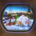
Here's a better picture, made just after turning on. I have seen better.
I have to turn up the iconoscope bias as it (or something?) warms up. It seems to work best with the iconoscope filament runnig at 5 to 5.7 volts RMS.
|
|
#15
06-21-2016, 11:03 AM
|
||||
|
||||
|
Yes, missing picture. Its only somewhat better. I'll try
again tonight. I measured the iconoscope grid current. It is OK at turn on, then climbs to a couple of microamps when the picture fades, in tirection that gas makes. Thus, only a marginally good tube. Nevertheless, its a working demo. Ad placed for better 1846 iconoscope in the "usual suspect" classifieds.
|
| Audiokarma |
 |
| Thread Tools | |
| Display Modes | |
|
|


 Linear Mode

