
|
|
|
#1
 05-29-2017, 03:35 AM
|
||||
|
||||
|
Starting work on a GE 800 Locomotive.
I wanted a project that didn't need a massive amount of cabinet work for a change so I dug out this Locomotive that I've had for quite a while.
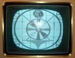
I'm not sure what the difference is between the 800 and the 805, Brass vs Aluminum grille perhaps? Mine is Aluminum but there are no tags on this set to identify it for sure. It has a 10BP4 that test's like new, probably a replacement because I believe these came with a 10FP4 as original equipment. Anyhow, I brought it up semi slowly on the Variac while watching the current draw, at about 75 volts I heard the Oscillator kick in, at 90 I could draw an arc from the cap of the 1B3 but no light on the screen, at 100v I could see a faint line on the screen and tweaking the Ion Trap brought it up to a short, bright raster. It's always a good sign when a set shows this much life right out of the gate, bumping the line voltage to 110 fills out the width completely, a recap ought to bring it back to full life. Many of these sets are missing the top to the high voltage cage, this one is missing the side, luckily i have a spare chassis with that part on it. 
|
|
#2
05-29-2017, 10:41 AM
|
||||
|
||||
|
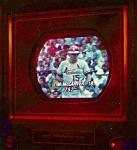
I have one of these and it's one of the best playing '40's TV's I've ever owned. No issue with it in any way and no fiddling with the controls. It started-out with troubles after it's first resto, and then my repairman went over it again and worked his magic on it! It plays like a period Admiral.
|
|
#3
05-29-2017, 01:52 PM
|
||||
|
||||
|
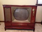
Mine is labeled "800 D"... it has a 3:4 mask and aluminum front panel. I think that I will get it out and play along. I think E/M has just restored one as well, cute little sets!
Here is mine, from old thread: Good players, the wood model on the right played well into the 90s with mostly original parts, now needs filter caps, however. jr Last edited by jr_tech; 06-06-2017 at 12:01 PM. Reason: found better pix
|
|
#4
05-29-2017, 04:15 PM
|
||||
|
||||
|
I found 800 and a large C stamped on the rear of the chassis so I guess it's a model 800, run C.
I have another chassis that I recapped about 20 years ago and then gave up on because all the controls were shot (and the cabinet was a mess), it still has all the nearly unused Sprague Atom Electrolytics in it so I will pull them out of that and put them into this, the film caps I will just replace with new, not worth the trouble of removing them.
|
|
#5
05-29-2017, 06:05 PM
|
||||
|
||||
|
I think mine is an 805. Mine has a brass front.
I started rebuilding mine last year. Took it off the bench when I got an antique Edison Triumph phonograph in bad shape. Hope to get back to my GE tv soon, again. 
__________________
"Tubes are those little glass things that light up orange unless there is a short.. Then they light up all pretty colors..." Please join my forum. http://www.tuberadioforum.com/
|
| Audiokarma |
|
#6
05-29-2017, 08:52 PM
|
||||
|
||||
|
I just finished restoring mine a few months ago. Mine was missing the model sticker on the bottom, but was stamped model 805 W on the chassis in black ink. It was a fun restoration, with only a few hard to get to caps. Mine has the brass plate on the front. Advice someone gave me, put some cardboard over the speaker, because they're easy to put your hand through.
|
|
#7
05-30-2017, 09:47 AM
|
||||
|
||||
|
Quote:
__________________
Tom C. Zenith: The quality stays in EVEN after the name falls off! What I want. --> http://www.videokarma.org/showpost.p...62&postcount=4
|
|
#8
05-30-2017, 05:27 PM
|
||||
|
||||
|
Brought mine slowly up on a variac... no light in any of the tubes... cleaned and deoxit the pins... half the tubes are lighting... found open heater resistor... got them all going.
Now getting about 7 kV on anode and most voltages are low, but it makes sound and somewhat of a short and VERY unstable pix. The cat is alive! Most solder joints on the set have never been touched (still painted red), it seems a shame to disturb these but re-cap job is definitely called for. great fun, jr Last edited by jr_tech; 07-07-2017 at 12:19 PM.
|
|
#9
05-30-2017, 07:15 PM
|
||||
|
||||
|
Quote:
|
|
#10
05-30-2017, 07:17 PM
|
||||
|
||||
|
Quote:
I was wondering about the red marks, assembly line marks to show a step completed?, or maybe anti tamper marks to prevent warranty fraud?
|
| Audiokarma |
|
#11
06-01-2017, 12:19 AM
|
||||
|
||||
|
As a matter of fact, I believe that is why the company painted those connections.
That chassis definitely needs a complete re capping. Those filament have me stumped. Sams only says 75 ohms. But hose resistors change resistors change resistance as they warm up. So, I'm mixed up as to what values of resistors to put in there. Bill Cahill
__________________
"Tubes are those little glass things that light up orange unless there is a short.. Then they light up all pretty colors..." Please join my forum. http://www.tuberadioforum.com/
|
|
#12
06-01-2017, 08:34 AM
|
||||
|
||||
|
Quote:
You can find the power by P=EI, P=(I^2)R, or P=R/(V^2)...Probably good to double that value as many power resistors get hot enough to unsolder themselves when they reach rated power. If you are worried about achieving a soft start, you could round that resistance up a bit, and or add a CL-90 inrush current limiter to the set.
__________________
Tom C. Zenith: The quality stays in EVEN after the name falls off! What I want. --> http://www.videokarma.org/showpost.p...62&postcount=4
|
|
#13
06-01-2017, 12:41 PM
|
||||
|
||||
|
A few comments and questions:
1. Possibly the red paint indicates a QC inspection... I have seen it on many high quality instruments from the WWII era. 2. 75 ohms in each heater string is about correct for average line voltage...I may add an additional resistance if necessary, depending mostly on what I read for CRT heater voltage, or protect the CRT heater with a TVS diode, see: http://www.videokarma.org/showthread.php?t=268968 3. I got full height by replacing the .04 cap (actually 2 caps in parallel) in the vert osc/amp. (the 4.3 meg resistor was ok). Nice to start the re cap job with a unit that makes a halfway decent, although unstable pix! 4. Finding some surprises where the circuit seems to match later models, The Riders schematic cannot be assumed to be 100% accurate. For example, that big cap shown in my underchassis pix in my second post between the tuner and the vertical output transformer (0.5 uf) is not shown... it bypasses the contrast control and is similar to the way the later 10T4 is configured. 5. Tom, did you get the .0022 cap mounted on the flyback? jr Last edited by jr_tech; 06-01-2017 at 01:18 PM. Reason: correction: pix is on my second post
|
|
#14
06-01-2017, 12:46 PM
|
||||
|
||||
|
Quote:
__________________
Tom C. Zenith: The quality stays in EVEN after the name falls off! What I want. --> http://www.videokarma.org/showpost.p...62&postcount=4
|
|
#15
06-02-2017, 10:28 PM
|
||||
|
||||
|
I replaced nearly a dozen paper caps tonight.
I lost a little vertical sweep but gained some video signal, the horizontal frequency is way off, there are multiple images across the screen, but the vertical seems to lock. Regaining the video probably had more to do with cleaning the tuner than replacing capacitors, I didn't change any in the i.f. section as far as I know.
|
| Audiokarma |
 |
|
|


 Linear Mode

