
|
|
|
|
|
#1
 11-13-2017, 06:53 PM
|
||||
|
||||
|
Thanks for posting the link and the “T13”. There was a reference earlier to the “service clinic” or “white book” booklet. Do you have that as well?
I’ve have the service clinic for the CTC-7. I have the Sams for both sets and the “Field service guide” manuel.
__________________

Last edited by etype2; 11-13-2017 at 06:58 PM. 
|
|
#2
11-14-2017, 03:54 PM
|
||||
|
||||
|
Quote:
To my knowledge, these are the only two official service documents regarding the CTC-2B. There may be others that I'm unaware of, but I doubt it. I believe Nick has a copy of the Service Clinic, but given how dismissive you were of his attempt to help, he probably won't bother to post it. I wouldn't blame him either... Last edited by benman94; 11-14-2017 at 04:28 PM.
|
|
#3
11-14-2017, 05:21 PM
|
||||
|
||||
|
Quote:
__________________
Evolution... 
|
|
#4
11-14-2017, 05:28 PM
|
||||
|
||||
|
Quote:
|
|
#6
11-15-2017, 11:36 AM
|
||||
|
||||
|
These sets were in service for around a decade when the X-Ray alarmists got started...A pre X-ray scare HV reduction I'd buy as merited, but any X-ray scare reductions I'd regard as superfluous and 'not running the set as it would have been during most of it's intended service life'. I rather see a CTC-2/CTC-2B doing what it would have done in the 1954-1963 time frame, than what it would do in 1967-1975.
__________________
Tom C. Zenith: The quality stays in EVEN after the name falls off! What I want. --> http://www.videokarma.org/showpost.p...62&postcount=4
|
|
#7
11-15-2017, 11:53 AM
|
||||
|
||||
|
Quote:
I still have yet to see a logical reason to run this set at less than 25 kV, but plenty to run it at spec... But if you don't believe me, defer instead to John Yurkon, a physicist as well, who has done actual testing on CRTs: http://www.videokarma.org/showthread.php?t=112954
|
|
#8
11-15-2017, 01:46 PM
|
||||
|
||||
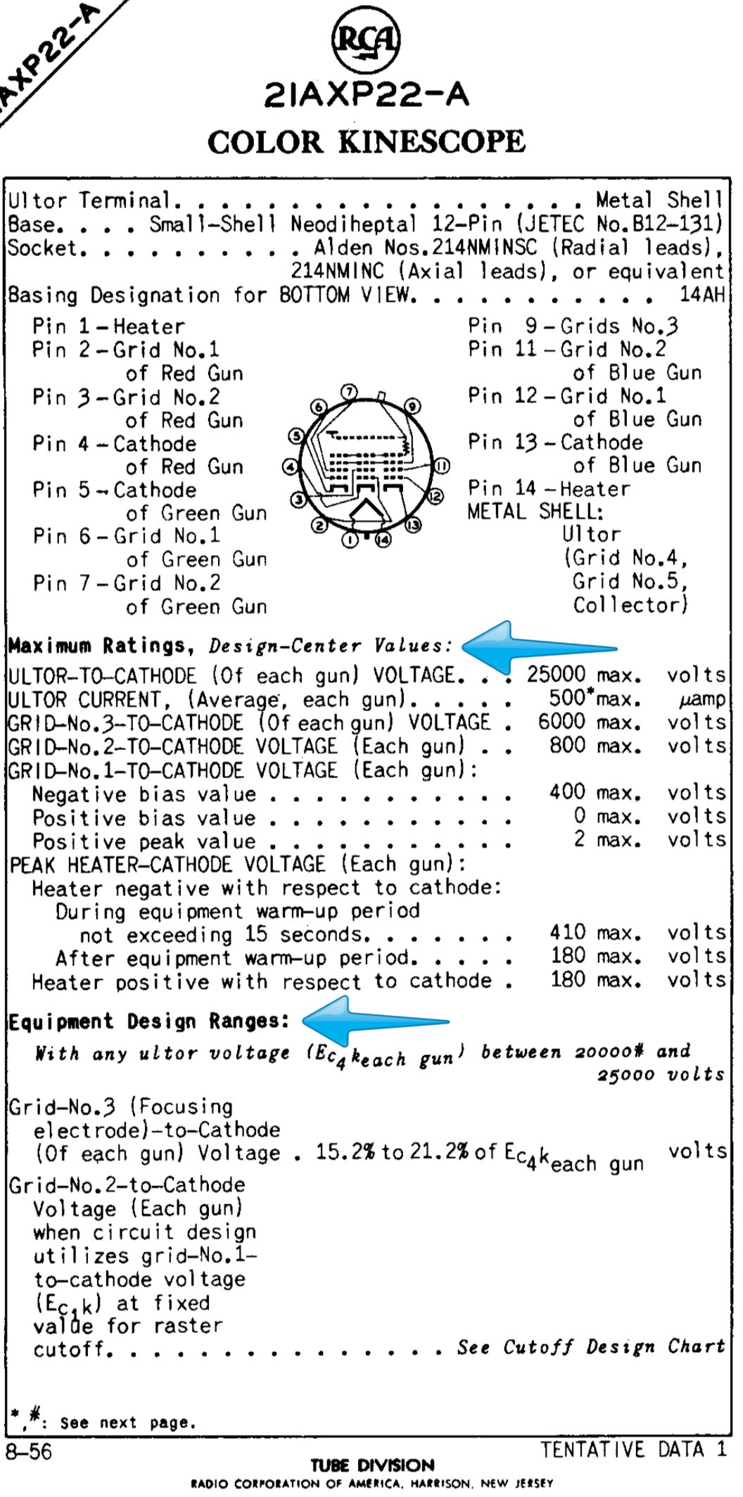 I see that on pages 6 and 17 of the T13, RCA calls for setting the ultra voltage at 25KV. What I’m trying to understand is how does this relates. In the RCA data sheet for the 21AXP22A, RCA states: max 25KV ultor voltage. RCA states: equipment design range with any ultra voltage 20 to 25KV. Look I’m not a tech, my 41 year career after the Navy was real estate law. Just trying to understand. I remember Mike telling me that the Sams procedure for alignment was incorrect, don’t remember the specifics. This would not be the first time service manual’s are incorrect.
__________________
|
|
#9
11-15-2017, 02:16 PM
|
||||
|
||||
|
Marshall,
Look again at the arrow in the datasheet you posted. The words "Design Center" are key here. The design center system of maximum ratings means it is completely safe to run the maximum allowed value. Design center means you can actually exceed the maximum value listed by about 10 to 20 percent, and provides a built in safety margin for parts value variation, manufacturing tolerances in parts, etc
|
|
#10
11-15-2017, 02:24 PM
|
||||
|
||||
|
Look at this datasheet for the 15HP22: https://frank.pocnet.net/sheets/084/1/15HP22.pdf
CBS ran them at 20 kV ultor voltage. Look at this datasheet for the 15GP22: https://frank.pocnet.net/sheets/093/1/15GP22.pdf Every manufacturer ran them at 20 kV (19.5 kV in the case of RCA, which is a negligible difference). Look at this datasheet for the 10FP4 CRT. Most 10 inch sets ran them right at 10 kV or damn close to it. https://frank.pocnet.net/sheets/201/1/10FP4.pdf Do you see the pattern. Running at design center maximum is perfectly fine, and in the case of a CRT, often desirable.
|
| Audiokarma |
|
#11
11-15-2017, 03:00 PM
|
||||
|
||||
|
Your last two posts took the words out of my mouth before I could write them, Ben.
To add to your running at design center max being desirable. Most manufactures tried to do that for a couple of reasons: Brighter picture, and CRT life. The cathode material of a CRT has a somewhat finite number of electrons it can emit before the emissive material is depleted. The higher the HV the less gun current is needed for a given brightness setting, the less current the fewer electrons needed from the cathode for the same result, the fewer electrons used for desired result the longer the CRT life. Also I'm not trying to knock your tech, but I remember you quoted your tech as saying that the HV regulator "shunts the excessive voltage" which conceptually is wrong. The regulator shunts current not voltage from the HV line to ground. You see every power supply has to obey the laws of Thévenin...That is there is no ideal voltage source. Every voltage source has an internal resistance, and that internal resistance forms a voltage divider with the load (CRT+HV reg tube). In the case of varying loads (such as a CRT) the output voltage varies as a function of load current drawn through internal supply Thévenin resistance. The HV reg is configured to attempt to increase it's relative current draw instep with decreases in CRT current draw (caused by video content), and decrease when the CRT increases. If the current through a Thévenin resistance is held constant (which is what the HV reg tube is meant to do) then the output voltage of the supply is also held constant. There is also an average current to the HV reg that is adjusted by the HV level pot....The lower you set the HV level the higher the constant/average current (sum of CRT and HV reg tube) is on the HV winding of the flyback. The Thévenin resistance lives in the fly windings in the case of a TV like this, and thus the higher the HV current you put through it the higher the heat and strain on the flyback. Many RCA flybacks were being pushed hard by design, adding to it does not strike me as desirable.
__________________
Tom C. Zenith: The quality stays in EVEN after the name falls off! What I want. --> http://www.videokarma.org/showpost.p...62&postcount=4 Last edited by Electronic M; 11-15-2017 at 03:03 PM. Reason: typo
|
|
#12
11-15-2017, 03:32 PM
|
||||
|
||||
|
Quote:
The primary issue is that the red phosphor was extremely inefficient. The underlying physical process of exciting a phosphor is more efficient with higher energy electrons, which in turn demands higher anode voltage. Side bar: This is the reason that many Zenith Walton owners have resorted to connecting the B+ for the eye tube (the rare Zenith specific one, 6T5 maybe?) with 500+ volts from a solid state source hidden in the set. With a burned P1 Willemite phosphor, that 500+ volts can bring back sufficient brightness. The cathodes in these tubes are usually still quite strong. Also keep in mind that the shadow mask blocks a vast majority of the electrons leaving the cathodes. They simply strike the shadow mask and return through the HV lead back to the chassis, never striking a phosphor and therefore never producing light. This is why the Lawrence Tube, the Apple tube, the Sony Chromatron and Trinitron, etc were explored. RCA took a different approch. Modify the existing shadow mask design to a degree and develop newer brighter more efficient phosphors. This of course culminated with the rare earth types. Another note about design center: one of the biggest variables in those days was the line voltage. It could range from 105 V to 120 V at the outlet. In most places this issue has been corrected, and the tolerance is nearer to 120 +/- 5% at the service drop to the house. This variability circa 1954 caused proportional shifts in filament voltage and B+. If you're one of the unlucky folks that lives at the end of a rural circuit serviced by DTE or Consumers, the situation hasn't changed at all since 1954...
|
|
#13
11-15-2017, 04:16 PM
|
||||
|
||||
|
Good information flowing ...
Just read a 1954 paper by RCA last night. This particular tubes shadow mask, 21AXP22 blocks 85% of the electrons. This same figure was presented to the IEEE in a paper entitled THE PDF CHROMATRON-A SINGLE OR MULTI-GUN TRI-COLOR CATHODE-RAY TUBE by Robert Dressler from the PROCEEDINGS OF THE I.R.E. VOL.41, NO. 7, JULY, 1953, priniple engineer at Chromatic Television Laboratoriess Inc., developers of the Chromatron tube. The slot mask was an effort by American manufactures to increase the electron flow to the phosphors. Like I said previously, Im taking everything said seriously. We will curtail running the 21AXP22 until I have a chance to sort all of this out with Mike. He is about to have a second surgery and dont want to bother him. Any comments about the latest screenshots after the slug was adjusted?
__________________
|
|
#14
11-15-2017, 04:22 PM
|
||||
|
||||
|
Quote:
As far as the screenshots go, I can tell, especially in comparison to the CTC-7, that the image is on the dim side. Otherwise they look alright.
|
|
#15
11-17-2017, 01:00 AM
|
||||
|
||||
|
21CT55 Slideshow
See the slideshow at the bottom of this link page.
https://visions4netjournal.com/vinta...tv-page-two-2/
__________________
|
| Audiokarma |
 |
|
|


 Hybrid Mode
