
|
|
|
#76
 05-03-2018, 02:09 AM
|
||||
|
||||
|
Quote:

|
|
#77
05-03-2018, 05:12 PM
|
||||
|
||||
|
No problem! It's a clever idea. I may get a chance to try it in a day or two.
Regards, Phil Nelson Phil's Old Radios https://antiqueradio.org/index.html
|
|
#78
05-04-2018, 07:10 PM
|
||||
|
||||
|
Quote:
I reversed only the horizontal wires (pins 5 and 7 in the previous schematic). That should answer the basic question. Here, they are connected normally: 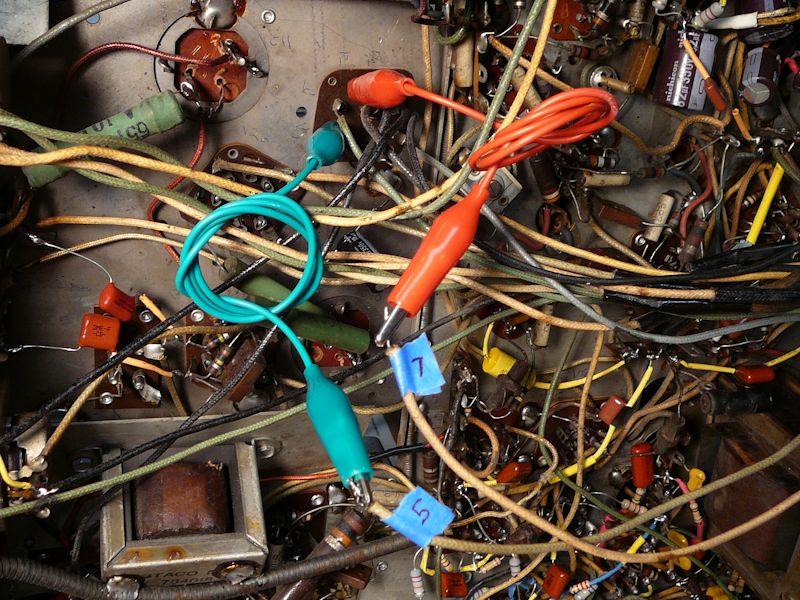 Horizontal wires connected normally: 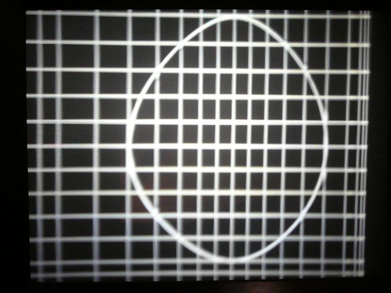 Horizontal wires reversed: 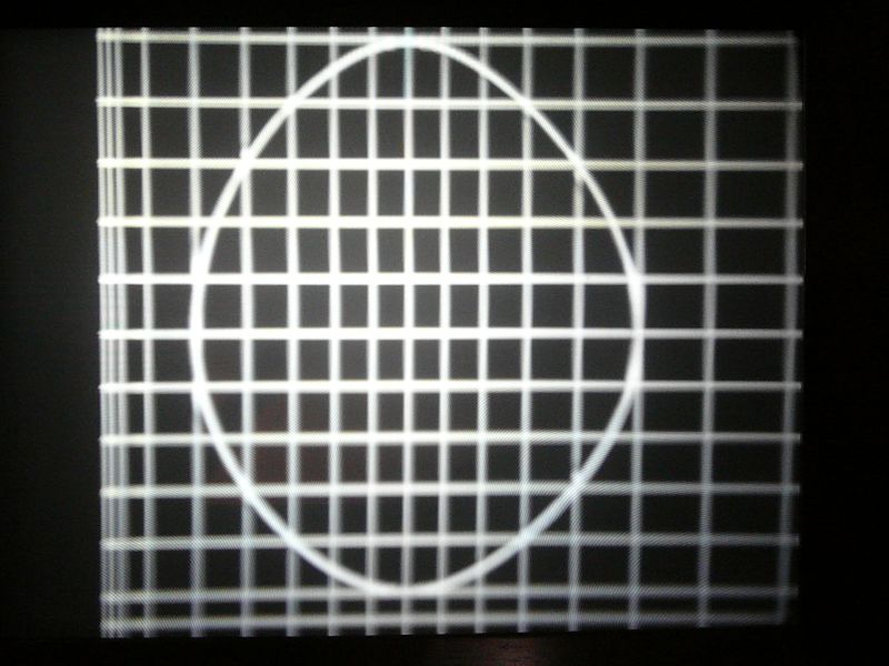 The distortion flips horizontally, so clearly the big defect lies in the electronics. Thanks for suggesting this simple test, Josef! That's actually a relief. Although I don't have an immediate solution for the electronics, that sort of problem-solving should be easier than trying to fiddle optical parts inside the Protelgram "black box" without the factory jigs originally used to align them. Now I will put the three chassis back onto the workbench and resume my homework (testing voltages, etc.). Regards, Phil Nelson Phil's Old Radios https://antiqueradio.org/index.html
|
|
#79
05-30-2018, 04:26 PM
|
||||
|
||||
|
I finished my voltage-testing homework, checking all the voltages against the chart in the Sams manual (https://antiqueradio.org/art/Sams%2090-6.pdf). This spreadsheet shows the test results (ideal = voltage from the manual, actual = measured voltage):
https://antiqueradio.org/art/Emerson...nVoltages.xlsx The tests were done with the line voltage held at 117VAC on a variac. I turned down the brightness and audio volume controls; the horizontal & vertical hold controls were set for a normal picture. Not surprisingly, given that most of the TV works fine, most of the voltages are in about the right ballpark. The filament voltages look somewhat low everywhere, measuring about 5.7 - 5.8VAC rather than 6.3 volts. None of the other results looks like a big red flag, although possibly I'm misinterpreting something. I'm back to seeking a cause for the bad horizontal linearity. As mentioned earlier, adding a cap across the width coil increased the width and somewhat affected the linearity, but it wasn't a miracle cure. I suppose I could go back and fiddle with different values for that cap. There isn't much else to tweak in that circuit, although I see two caps on either side of the horizontal linearity adjuster (C-65 and C-64 in the Riders schematic below). Those wouldn't be difficult to change, if there's a reason to try that. Any other ideas? Phil Nelson Phil's Old Radios https://antiqueradio.org/index.html 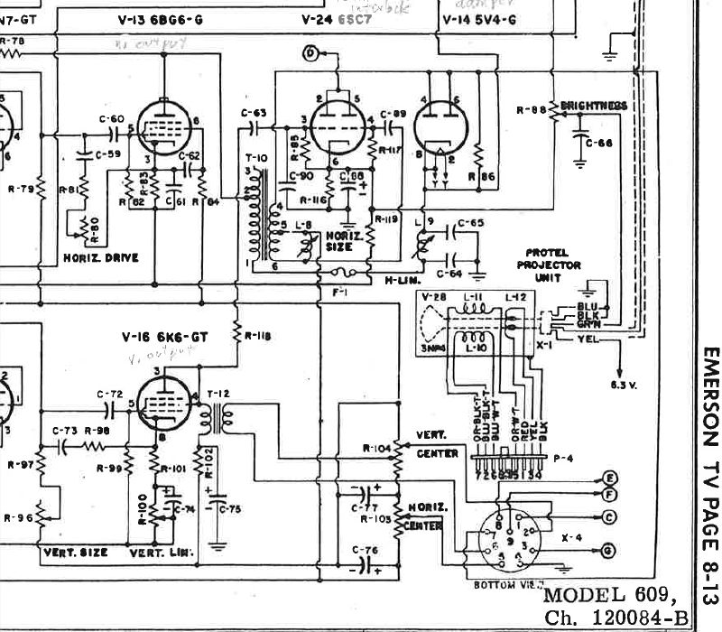
|
|
#80
05-30-2018, 05:13 PM
|
||||
|
||||
|
What type of caps and values are C-64 and C-65? If you have no way to test, substitution is surely a good idea - after all, that coil they're attached to does say H lin.
|
| Audiokarma |
|
#81
05-30-2018, 09:25 PM
|
||||
|
||||
|
The originals were 600-volt rated paper caps, which I replaced during the first recapping pass. C64 is .035 and C65 is .05, which look like pretty standard values for those caps in my old TV books.
I replaced them with modern film caps (the brown chiclet style) rated for 630V. I paralleled two caps to make up the .035 cap. I guess it's possible that one of the replacement caps is bad or that I (shudder!) installed a wrong value. I can disconnect and test them. Phil Nelson Phil's Old Radios https://antiqueradio.org/index.html Last edited by Phil Nelson; 05-30-2018 at 09:29 PM.
|
|
#82
05-30-2018, 09:42 PM
|
||||
|
||||
|
I have less confidence that they are the problem, since you replaced them, but it doesn't hurt to double check. There seem to be two things going on: left and right not the same width (usual sort of linearity problem), and sides much wider than the center. I don't understand the circuit well enough to point to a possible cause or causes.
Did you replace C-76 and C-77?
|
|
#83
05-30-2018, 10:28 PM
|
||||
|
||||
|
C76/C77 are 1000-mfd/15V electrolytics, which I replaced with new 25V-rated electrolytics. All paper & electrolytic caps have been replaced.
Phil Nelson
|
|
#84
05-30-2018, 11:08 PM
|
||||
|
||||
|
Quote:
__________________
Tom C. Zenith: The quality stays in EVEN after the name falls off! What I want. --> http://www.videokarma.org/showpost.p...62&postcount=4
|
|
#85
05-30-2018, 11:44 PM
|
||||
|
||||
|
They are specified as 600V in both the Sams and Riders parts lists, for what thats worth.
Phil Nelson
|
| Audiokarma |
|
#86
05-31-2018, 12:28 AM
|
||||
|
||||
|
Quote:
|
|
#87
06-20-2018, 12:33 AM
|
||||
|
||||
|
Quote:
 It's one of those guys that stands upright inside the high voltage cage. 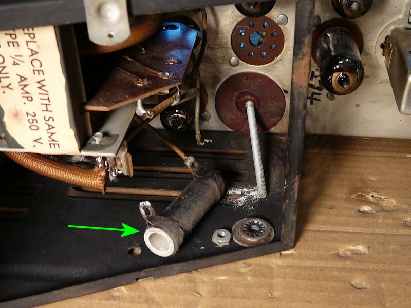 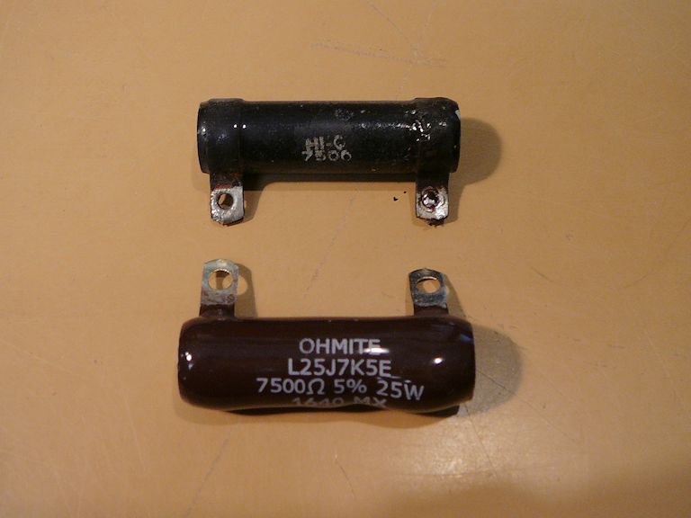 Replacing it cured the worst horizontal geometry problems, but then the width was insufficient. Earlier in the project, I had removed a .25 paper cap that someone tacked in parallel with the width coil (L8).  I experimented with a decade box and found that .25 was indeed about the right value to bring the width back into range. 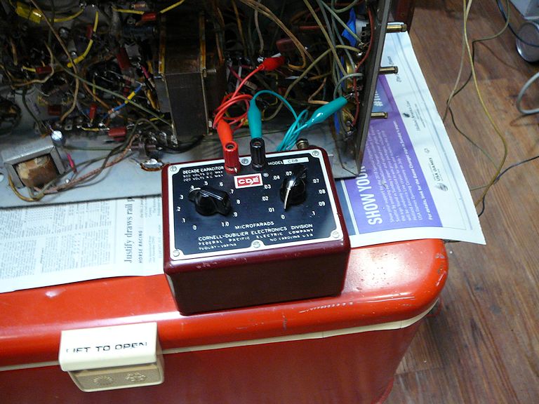 I guess the guy who added that cap was onto something  There's more tweaking to do -- there is still a very slight crushing of width on both far edges -- but I have a watchable picture for the first time in this project. 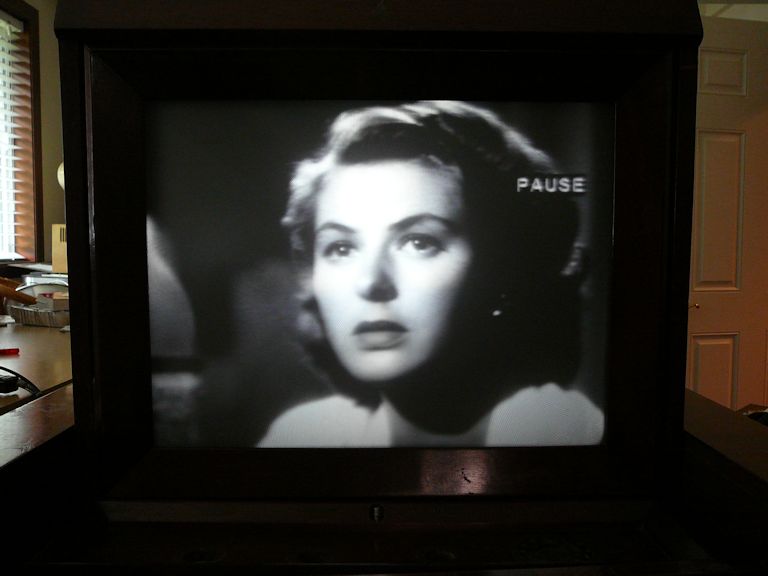 Yay! Phil Nelson Phil's Old Radios https://antiqueradio.org/index.html
|
 |
|
|


 Linear Mode

