
|
|
|
|
|
#1
 06-20-2018, 01:57 PM
|
||||
|
||||
|
For a quick test you could bridge the 7.5k with a much lower wattage resistor, perhaps starting with something like 20 to 50k and observe the change (if any). Also a lower wattage resistor, something like 500 to 1000 ohms could be added in series for a quick test.
 jr 
|
|
#2
06-20-2018, 03:09 PM
|
||||
|
||||
|
You can't do it with the high wattage components, but if it were lower power, simultaneous adjustment with both a capacitor decade box and a resistor decade box could make short work of a problem like this.
This has been deprecated in the past as "dec-box engineering" because there is no pre-calculation of the correct values. But it need not be looked down on if two things are true: 1) You already have a reasonable starting point 2) You are observant enough to understand which aspect of performance is changing as you make the adjustment. In a hypothetical example, you might note that a small resistor change modifies overall width (and is it larger or smaller) without much change in edge compression, while the cap affects both width and compression, and adjust first the cap in a small step to get better edges, then the resistor in a compensating small step to get the right width, and so on. NOTE: you also have to be aware whether the transient condition of an open circuit while switching the dec box could cause a destructive fault. In your case, you already know nothing is being destroyed even with the components open-circuited. Last edited by old_tv_nut; 06-20-2018 at 03:12 PM.
|
|
#3
06-20-2018, 10:37 PM
|
|||
|
|||
|
Phil, it might be worth trying the old "seven seconds off & back on" test. Does the raster come back at full width, or is it slow filling out? If unusually slow, are there any peculiarities with the lin during fill-out?
|
|
#4
06-21-2018, 10:52 AM
|
||||
|
||||
|
Quote:
|
|
#5
06-21-2018, 11:50 AM
|
|||
|
|||
|
Quote:
Same principle as the Life Test on a tube tester which drops the heater voltage down. This was followed by the 'tap test' of each tube to show up any arcing (like the damper), intermittent shorts etc. Made service calls more effective with less chance of call-backs.
|
| Audiokarma |
|
#6
06-21-2018, 02:20 PM
|
||||
|
||||
|
OK, I'll try the seven-second test later today and observe the results.
I spent some time yesterday playing with different values for R86, using a handful of 25-watt resistors that I picked up locally. It is a cumbersome and very slow process, to clip a resistor (or series-ed resistors) into place, slide the chassis back into position, turn the set back on, observe the result, and try to compare the pattern to what you saw before. I tried taking photos with the camera on a tripod, and noting the resistor values for later comparison. Subbing the capacitor values was so much easier with a decade box, where I could keep my eyes on the screen and flip between different values, back and forth, looking at different parts of the screen, etc. Anyway, yesterday's results were not very informative. When I put a crosshatch pattern back on, I realized that the linearity wasn't quite as good as I remembered. I also realized that I had begun with the TV in a somewhat random state -- that is, with the various controls set to produce an image with best horizontal linearity & centering. I had also left in the .22 cap across the width coil. What kind of baseline is that? Perhaps it would make more sense to remove that .22 cap and center ALL of the pertinent controls, then repeat the rigamarole of subbing the cap and resistor values, looking for changes that make sense. There are lots of variables in this equation. In addition to the horiz width and linearity adjusters, you have the horiz centering and horiz drive adjusters, all of which affect width and linearity to some extent. Not to mention the mechanical centering adjusters on the optical box. Does anyone have a clear idea what changes you would expect to see on a perfectly-linear set when changing the value of this damper resistor (R86)? Phil Nelson
|
|
#7
06-22-2018, 11:01 AM
|
||||
|
||||
|
I think it means the first section is 5300, in series with a 500 and another 500, so total is 6300. Power is I squared times R, so if the current is approximately the same magnitude for all settings, the smaller resistors in the series string need proportionally smaller wattage. So, one tenth the R --> one tenth the watts.
|
|
#8
06-22-2018, 12:57 PM
|
||||
|
||||
|
Ah, another forehead-slap moment. Lower resistance means lower wattage, duh.
I reviewed the photos that I took while experimenting, and it's clear that increasing the resistance stretches the left half of the image, while decreasing resistance squeezes the left half. Changing the resistance also changes the overall width somewhat. And it does not really cure the non-linearity I'm seeing. The far left edge is still squeezed, etc. And there is an additional variable -- the value of the .22 cap added to increase the overall width. Finding the best setting looks like a very iterative process: -- Try new resistor value -- Adjust the width, horizontal linearity, and horizontal drive controls for best linearity -- Try another resistor value -- Adjust all the etc. -- Repeat, repeat (maybe also adjusting the value of the .22 width-coil cap to see how that effects everything) That would be simpler with a direct-view TV, which you could plop onto the workbench and easily view while adjusting. Not so much fun when you are crouching on the floor to make adjustments and peering around to view the results in a little serviceman's mirror on the other side of the cabinet. OK, enough whining already! I hope to make some progress this weekend. Phil Nelson Quote:
Last edited by Phil Nelson; 06-22-2018 at 03:38 PM.
|
|
#9
06-22-2018, 03:35 PM
|
||||
|
||||
|
Quote:
*My college only stocked 1/2W resistors so when the maths for a circuit design called for a 10W+ resistor that needed to last 30min of various measurements and tests without burning up we had to get creative with series-parallel combos to get a safe wattage...And the professors and parts room folks always wondered why there were so many off tolerance resistors in stock.  What kind of connectors does the main chassis use to hook into the cabinet projection system?... If it is just a set of octal and or Fat-pin tube base/socket connectors (and maybe a CRT socket/HV lead) why not make 5'-12' extender cables so you can keep the cabinet next to the bench and have the chassis on the bench connected to the cabinet for easy adjustment and testing....I did just that when I was working on my 21CT55 to make things easier for me.
__________________
Tom C. Zenith: The quality stays in EVEN after the name falls off! What I want. --> http://www.videokarma.org/showpost.p...62&postcount=4 Last edited by Electronic M; 06-22-2018 at 03:43 PM.
|
|
#10
06-22-2018, 11:15 PM
|
||||
|
||||
|
Extender cables would be handy, although not super-easy.
Two of the three cables would be do-able. The yoke connector is 9-pin, roughly the size of an octal socket with a ninth pin near the center. A second cable goes to the HV power chassis with a 4-pin connector. I don't have such connectors on hand, but I suppose you could scrounge them somewhere. The CRT cable looks tricky. It uses a funky 5-pin connector of a type I haven't seen before. The cup has terminals on the inside and it slides over the butt end of the CRT, which has little metal tabs around its edge.  Weird,wild stuff, as Johnny Carson used to say. You wouldn't need an extender for the HV cable to the CRT second anode, since that doesn't come from the main chassis. It only goes between the two boxes of the Protelgram unit (HV power chassis and optical box holding the CRT). Phil Nelson Phil's Old Radios https://antiqueradio.org/index.html
|
| Audiokarma |
|
#11
06-22-2018, 11:56 PM
|
||||
|
||||
|
CRT base appears to be a euro tube connector...I once was at a swapmeet where someone had some really old Brittish or German tubes with that style of connector...Some had a different number of 'pins'. I had the same impression when I saw them there for the first time...
In your shoes if I did not much like the set, badly wanted/needed service convenience, or had a situation where the wiring to the interconnects was damaged or otherwise unoriginal I'd be tempted to cut the harnesses and insert some other connector that I could easily make (or use an existent) extender for...In any case it's your set, your back/knees, your call.
__________________
Tom C. Zenith: The quality stays in EVEN after the name falls off! What I want. --> http://www.videokarma.org/showpost.p...62&postcount=4 Last edited by Electronic M; 06-23-2018 at 12:04 AM.
|
|
#12
07-03-2018, 04:42 PM
|
||||
|
||||
|
There is something unusually appropriate about how a B&W movie looks on a period projection...TV.
 
__________________
Tom C. Zenith: The quality stays in EVEN after the name falls off! What I want. --> http://www.videokarma.org/showpost.p...62&postcount=4
|
|
#13
07-03-2018, 08:24 PM
|
||||
|
||||
|
I agree Tom. I think the key word is "projection". What we see is an intensification of the brightness in the center if the screen and less in the outer regions. I would think in both the movie theater and the projection TV you have this effect to some degree due to the use of projection lenses taking a small image and projecting it magnified onto a screen.
In any event I love the way it looks.
__________________
Vacuum tubes are used in Wisconsin to help heat your house. New Web Site under developement ME http://AntiqueTvGuy.com
|
|
#14
08-08-2018, 01:06 AM
|
||||
|
||||
|
OK, I'm declaring this project finished. The picture is very watchable and I got around to touching up the cabinet:
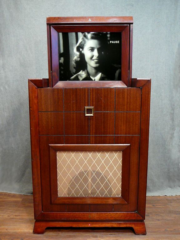 This article provides many details: https://antiqueradio.org/art/Emerson...onFinished.jpg One question in parting: why did Emerson use a pattern of tiny concentric grooves in the face of the display screen? In this extreme close-up, I heightened the contrast to exaggerate the circular pattern, which is imperceptible at a normal viewing distance:  I have a couple of guesses (see article above), but optics is not my strong suit, and I haven't restored any other projection sets, so if you know the answer, kindly clue me in! Regards, Phil Nelson Phil's Old Radios https://antiqueradio.org/index.html Last edited by Phil Nelson; 08-08-2018 at 01:48 AM.
|
 |
|
|


 Hybrid Mode
