 |
|
|
|
#1
|
||||
|
||||
|
Video Polarity and Direct Injection
I have a set into which I'd like to directly inject video. My problem is the set only has one video amplifier tube so the video polarity at the grid of the video amp is positive. Injection after the video amp isn't doable as I don't have enough gain, and injection before the video amp isn't doable because the polarity is backwards. Can anyone tell me how flipping the polarity on composite video might be accomplished so that I may inject positive video into the grid of the video amp?
__________________
John |
|
#2
|
|||
|
|||
|
A phase inverter using a single triode shouldn't be too hard to slap together. No doubt the collective wisdom on here can ace a quick design.
A factoid worth bookmarking is that a tube's plate is opposite phase from the grid, while the cathode (if unbypassed) is in-phase with the grid. |
|
#3
|
||||
|
||||
|
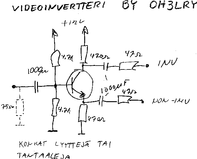
Or with a single transistor:
Video Inverter near the bottom of the list..... http://www.hobbyprojects.com/A/video.html I built a crosshatcht generator using an EDN magazine "Design Idea" and tried the video out with a salvaged Astec modulator - no joy, so I rigged up a 2N2222A as an inverter, and voila.... BTW, it still works, and is more stable than my RCA portable unit...
__________________
Brian USN RET (Avionics / Cal) CET- Consumer Repair and Avionics ('88) "Capacitor Cosmetologist since '79" When fuses go to work, they quit! Last edited by Findm-Keepm; 12-08-2016 at 09:23 PM. |
|
#4
|
||||
|
||||
 Would a 2N4401 work in that circuit?
__________________
John |
|
#5
|
||||
|
||||
|
Sure - any low gain (hfe<500) NPN should work. If you get any ringing, try ferrite beads on the base and collector leads.
I built my 2N2222A inverter on a double sided PCB, with the bottom as a ground plane, and "Manhattan" style construction on the top. The circuit I used was in "Circuits Cookbook" from 1967.... The whole circuit takes advantage of the common emitter configuration for inversion - and - the common collector configuration gives you the non-inverted video on the emitter. Two in one! https://en.wikipedia.org/wiki/Common_emitter https://en.wikipedia.org/wiki/Common_collector
__________________
Brian USN RET (Avionics / Cal) CET- Consumer Repair and Avionics ('88) "Capacitor Cosmetologist since '79" When fuses go to work, they quit! |
| Audiokarma |
|
#6
|
|||
|
|||
|
Probably need some gain
__________________

|
|
#7
|
|||
|
|||
|
That means that the circuit is designed for a 75 ohm input 1 volt video source (standard).
__________________

|
|
#8
|
||||
|
||||
|
Quote:

__________________
John |
|
#9
|
||||
|
||||
|
You probably want to actually install the 75 ohm resistor, so that your DVD player or other source is seeing the proper load impedance.
The exception would be if multiple inputs are "daisy chained" from a single video source. Then you install the 75 ohm terminator across the last input in the chain. |
|
#10
|
||||
|
||||
|
Transmission line theory 101 terminate your line with it's characteristic impedance to prevent reflections, ringing, reduced signal at terminals etc...Might be a good idea to brush up on (or look up the basics of) transmission line theory. If you are ever running a wired signal more than a few feet (especially if it is more than a tiny fraction of wavelength), or transmitting, T-line theory is crucial.
__________________
Tom C. Zenith: The quality stays in EVEN after the name falls off! What I want. --> http://www.videokarma.org/showpost.p...62&postcount=4 |
| Audiokarma |
|
#11
|
|||
|
|||
|
Question.
What is the polarity at the CRT? Are you looking at the schematic or a scope?
The CRT should be positive. Which means the driver tube input should be negative. The output of the detector is usually negative, because it is transmitted that way. (Sync is peak power.) Some of those detector circuits produce 5V of video.
__________________

|
|
#12
|
||||
|
||||
|
Quote:
*In fact color sets used both at once to effectively mix the color difference and monochrome signals into RGB in the electron gun to save a few signal tubes in the design.
__________________
Tom C. Zenith: The quality stays in EVEN after the name falls off! What I want. --> http://www.videokarma.org/showpost.p...62&postcount=4 |
|
#13
|
||||
|
||||
|
Quote:
__________________
John |
|
#14
|
||||
|
||||
|
A common deliberate use for the variable emitter impedance is in an IF stage with Automatic Gain Control (AGC). Even then, an emitter resistor is generally used, but the emitter also has an AC bypass capacitor directly to ground. The AGC feedback voltage is applied to the base of the transistor to vary the current in the transistor. This works fine as long as the IF signal is small compared to the DC bias, so the signal itself doesn't cause a variation in gain (which results in distortion). So, you may see AGC applied to the early IF stages and not to the last stage.
Because the video you want to amplify (1 volt) is large compared to the base-emitter drop (0.7 volts) it definitely could cause distortion; but when applied to the combination of the base-emitter junction and the emitter resistor, the emitter resistor keeps things linear. |
|
#15
|
|||
|
|||
|
Yeah, the emitter resistor all makes perfect sense now. The stuff I built decades ago was all small-signal devices, and low supply voltage (like 3 to 6 V). I was locked into the 'no emitter resistor' pavlovian habit. Moral of story: Dont be stoompid
|
| Audiokarma |
 |
|
|