
|
|
|
#1
 07-06-2023, 02:40 PM
|
||||
|
||||
|
Zenith 19" Chromacolor II service suggestions
Someone gave me a 19" 1978 model K1924W with chassis 19KC50. They said it didn't work, but when I powered it on it's basically working, but with a very washed out picture and retrace lines. With no signal it has a very bright raster so I've concluded the CRT is in good shape. At this point I have not replaced a single component. I'm thinking AGC but I don't currently have a service manual. I'm wondering what the difference is between Zenith service CM-107 and CM-107S1? 19KC50 is listed on the cover of both service manuals. More than likely a few electrolytic capacitors need replacing. Any suggestions from those that have worked on these would be greatly appreciated.
[edit] Forgot to mention the sound is crystal clear so that probably rules out AGC. Last edited by Kevin Kuehn; 07-06-2023 at 02:45 PM. 
|
|
#2
07-06-2023, 03:18 PM
|
||||
|
||||
|
AGC won't cause retrace lines.
Later CCIIs had a kine driver board (9-89?) that used a ceramic thick film IC instead of discrete transistors, and those were a pain in the ass. Same with the CRT socket. Some were conventional and some had those pesky ICs. Do you have a pic of the chassis? I seem to recall an open electro in the Kine source circuit that would cause that issue. The cap was behind the swing down chassis. I may have the manual somewhere for that. John
|
|
#3
07-06-2023, 05:49 PM
|
||||
|
||||
|
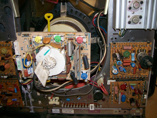
Here are some pictures of the chassis. Probably 10-15 years ago I replaced a cap behind the chassis on my folk's CCII although it's been so long I don't recall what the symptoms were. Can anyone recollect if the color setup switch is in the normal position(upper board on the left). When I flip that either way nothing seems to change.
Last edited by Kevin Kuehn; 07-06-2023 at 05:57 PM.
|
|
#4
07-07-2023, 08:57 AM
|
||||
|
||||
|
OK, I remember that model. The 9-89 kine board was eliminated and replaced with the CRT socket board. That one has those thick film ceramic IC on them.
Somewhere on that board is the source voltage for the kine outputs, typically 200VDC give or take 25V. That source is bypassed by a fairly low value electrolytic (10-22uf typical) at a higher voltage, like 250V. If that cap is bad, the voltage will be low which will force to tube to conduct higher and give you excessive brightness and retrace. The cap will be located in the chassis but if you can identify the source point on the CRT socket, you can follow the wire back to the cap on the chassis. A SM will also be helpful. The only CCII schematics I have left are the F models and earlier which won't be of much help. There is a G2 adjustment somewhere on that board, could be the yellow pot. Mark the pots with a Sharpie and turn them all counterclockwise one by one to see if maybe someone turned the G2 control up. Also tap lightly on that board to see if it's shock sensitive. Those ceramic ICs run very hot and the solder can deteriorate on the foil side of the board, but they can also fail where the IC pins are soldered to the printed ceramic substrate. With regards to the switch on the chroma board, in test position it floats the chroma osc so you can adjust R1018 control until the color bars are at their widest/most stable, then move the switch to normal to lock osc. Those switches get dirty so cleaning it with contact cleaner wouldn't hurt. You may not see any difference right now because your CRT is swamped. John EDIT: Although I tossed my Zenith manuals, I actually have the SAMS for it.. There is a 251V source going into the CRT socket module that you can measure across C1208 - a .01 disc cap near the jumper plug. From the chassis ground, check both sides of that cap. One side should have 251V and the other side zero (ground). If it's low, you can tap a 10uf at 250V cap temporarily across it (observe polarity) and see if the voltage rises. The kine bypass filter cap is CX228, a 10uf/350 and is an axial cap located on the bottom fixed section of the chassis, not the upper swing section. Swing the chassis down and the cap is on the bottom fixed section near the plug-in rectifier board. Careful when adjusting the yellow G2 pot - it's got 788V on one side of it, so use an insulated screwdriver or hex tool to adjust it, or just turn the TV off and rotate it to mid point to start. Last edited by JohnCT; 07-07-2023 at 11:37 AM.
|
|
#5
07-07-2023, 09:06 AM
|
||||
|
||||
|
Its an EFL in line CRT.
Most common for the symptom is 1) loss of the 200V source for the 3 video outputs. 2) too much G-2 volts. Resistors in divider open. 3) cold joints on the 9-88 module resistor pac. Cold joints on the CRT PCB also common. Resolder ALL of the film pacs. 73 Zeno  LFOD !
|
| Audiokarma |
|
#6
07-07-2023, 10:47 AM
|
||||
|
||||
|
Quote:
If either opens, it will push the G2 to boost voltage. John
|
|
#7
07-07-2023, 11:51 PM
|
||||
|
||||
|
Thanks for the suggestions. Tonight I re-flowed the solder on most of the CRT board. Also replaced the 10uf @ 350 volt electrolytic. That cap looked toasted and had leaked out, but now I'm still getting the same systems. The 3.6M and 1.8M divider resistors are very close to spec. The hi-low jumper below the yellow G2 control is currently shorting across the 3.6M resistor, but when moved to the low position there was very little change to the picture. The 251v source to the CRT board is only reading 20-40vdc when I vary the G2 control. I need to investigate further to see why it's this low. It's difficult to show a true representation of what the picture currently looks like because my camera keeps blanking it. I wish the set had a brightness control, but so far I'm not seeing anything obvious. If it's on one of the modules I could have easily missed it. User controls are very sparse.

Last edited by Kevin Kuehn; 07-08-2023 at 12:20 AM. Reason: Added more info
|
|
#8
07-08-2023, 02:12 AM
|
||||
|
||||
|
The 47 ohm wire-wound resistor that feeds the 10uf @ 350v cap was open. Replaced and now have 252vdc at the 251v source. Found the brightness control on the luminance board. The front picture control seems to be a sort of fine brightness control rather than contrast. Have things sort of dialed back in, at least it's a start. CRT appears to be healthy, and I found the original label that had fallen behind the fold down chassis.
Thank you gentlemen for your help in identifying the fault.   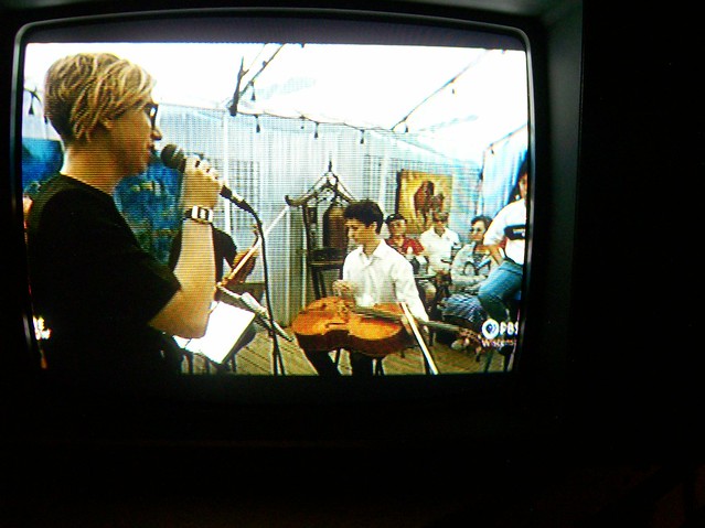 
Last edited by Kevin Kuehn; 07-08-2023 at 02:27 AM.
|
|
#11
07-09-2023, 01:05 PM
|
||||
|
||||
|
I'll bet the cap either shorted or became severely leaky and caused the resistor to open. As far as those CC2 sets, I was finding them all the time during the '90s. Now, they rarely show up. Currently, I have a 19" Delta-gun entry level set from '78, a motel set from '79 that has the same chassis as yours, and a '75 space command set. The main troubles I had with them were triplers, bad module contacts, and the big oil-filed cap in the power supply shorting.
__________________
http://www.youtube.com/user/radiotvphononut
|
|
#12
09-06-2023, 06:17 PM
|
||||
|
||||
|
I've been watching this Zenith on the work bench occasionally over the summer and it's been performing flawlessly. Today I decided to remove the chassis from the front cabinet to remove some dust bunnies before putting the back cover on, no big deal I thought. After reassembly I'm now noticing subtle moire in some solid colored areas. Seems to vary with picture content and sometimes I hardly notice it. In particular cartoons bring it out. First thought was did the degaussing PTC thermistor coincidentally die? I don't think I'm hearing the coil ping when I power on, but I'm not absolutely sure. I tried manually degaussing with my GC coil but that was no help. Anyone have any ideas? Picture attached emphasizes what I"m seeing in the green background. There's a horizontal shading or striping, somewhat with a stationary wave, and mostly in solid color areas.

Last edited by Kevin Kuehn; 09-06-2023 at 08:05 PM.
|
|
#13
09-07-2023, 07:41 AM
|
||||
|
||||
|
Moire started showing up on 14" chromacolor hybrids. If the customer
noticed it we were to touch up the focus, brite & contrast. If an in-line the G-2 also. If they still complained change the CRT. If you go looking for it its quite common. Blank stationary scenes are best to see it. Happens on other brands also, not just on Zenith EFL CRT's. Test for DGS is with a COLD set. Hook up an ANALOG AC ampmeter on the AC line or use a Power rite etc. Turn on the set while watching meter. The meter will swing very high then settle at apx .75 amps with normal pix. 73 Zeno LFOD !
|
|
#14
09-07-2023, 11:55 AM
|
||||
|
||||
|
Using my Amprobe on 6A scale I'm getting about 2.25A for 2 seconds on cold turn on. Then settles to less than 1A. Seem reasonable?
If moire is that common I'm gonna just try'n not worry about it. Thanks again for your expertise. Quote:
|
|
#15
09-07-2023, 02:45 PM
|
||||
|
||||
|
To verify that it's due to focus being sharp (and not a signal problem repairable in the circuitry), try adjusting focus to see if poorer focus reduces it, or try adjusting height or width to see if the moire fringes move.
|
| Audiokarma |
 |
|
|


 Linear Mode

