
|
|
|
#1
 01-04-2018, 02:32 PM
|
|||
|
|||
|
Thirty years ago I bought a Hallicrafters T-67 at a junk store in Washington DC. The seller warned me "careful, its a sparker!" Its been sitting in my attic ever since. After coming across the videos from bandersentv, I got motivated, pulled it down and looked it over. Yes there is significant carbon build up at the terminal atop the 1B3GT HV rectifier tube, but the flyback is pretty clean. However I noticed that there is no corona ring on the socket underneath the 1B3GT. Shouldn't there be one? Also looking at the SAMS picture, it looks like there is a cover over the 1B3GT top terminal - is this true? - mine's missing.

|
|
#2
01-08-2018, 06:29 PM
|
||||
|
||||
|
I looked through the old photos of my T-67 restoration, and I don't have one that shows the underside of the 1B3GT socket. I might be wrong, but I believe I have seen those sockets with and without corona rings. It's hard to imagine someone removing that part, so my guess is that yours never had a ring.
The following photo shows my 1B3GT from above, with a roll of something like fish paper covering the top cap. The T-67 is a decent performer when restored, so I'd encourage you to get yours running. Here are some restoration notes about mine: https://antiqueradio.org/hallit-67.htm Regards, Phil Nelson Phil's Old Radios https://antiqueradio.org/index.html 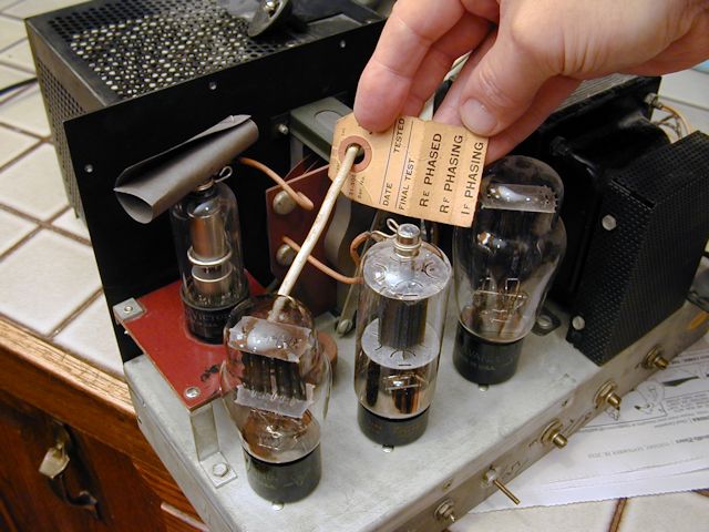
|
|
#3
01-08-2018, 08:24 PM
|
|||
|
|||
|
OOPs! Double post. Dumb, dumb.

|
|
#4
01-08-2018, 08:25 PM
|
|||
|
|||
|
Seems like corona rings were gradually phased out, as they're not really needed as long as solder joints are made smooth and ball-shaped with no pointy ends sticking out.
|
|
#5
01-09-2018, 08:40 AM
|
|||
|
|||
|
Phil and Old_coot88, thanks for the info! The socket looks to be a substantial one, made out of ceramic, and there is no scorching around the terminal lugs at the bottom. It looks like the lack of that fish paper at the top of the 1B3GT might have caused the arcing in mine. I've just repaired the curling veneer on the top where someone must have doused it with water when it was sparking. I'm definitely itching to get to the electronics, and will as soon as I finish with a Hammarlund 129x I'm struggling to align (the IF curves look as they should but the sensitivity is poor).
|
| Audiokarma |
|
#7
12-30-2019, 09:35 AM
|
|||
|
|||
|
Well I've been slowly working on the restoration of this TV and learning the electronic theory along the way. However I've discovered that the 4.5 MHz sound trap coil is open. It looks like someone has broken the wire in the center of the coil by mashing several turns at the top. I'll try to repair it, but I don't think I can. Since the likelihood of finding an exact replacement (Hallicrafters part #51A1037) is pretty slim, can I replace this with any 4.5 MHz sound trap coil? I see a few available on ebay.
Last edited by dcl0; 12-30-2019 at 10:17 AM.
|
|
#8
12-30-2019, 10:45 AM
|
||||
|
||||
|
You need a coil that will resonate with the connected capacitance, consisting of C53 (1.5 pf) plus whatever the input capacitance of the 6AU6 sound IF tube is. So, guessing total C is between 1.5 pf and 5 pf, that would be somewhere in the range of 25 to 83 microhenries (and probably toward the lower side, depending on the 6AU6 capacitance) if I did the math correctly.
|
|
#9
12-30-2019, 01:05 PM
|
|||
|
|||
|
Many thanks for the info. Does the 100 pf capacitor C54 need to be included into the calculation? or because it is in parallel with the 150K resistor, not a factor here? Can I alter the capacitor C53 to match whatever coil I can find? I have a Miller coil 1470 which ranges from 38-100 uH.
Last edited by dcl0; 12-30-2019 at 01:11 PM.
|
|
#10
12-30-2019, 02:28 PM
|
||||
|
||||
|
The 100 pF does not need to be in the calculation because it's in series with the grid capacitance. 100 pf is so much larger than the grid capacitance that the series combination is only a tiny bit smaller than the grid capacitance itself.
C53 is already very small, plus you will always have the grid capacitance loading the coil, so adjusting C53 smaller for a higher value coil will not work. However, if you get a lower value coil, you could try increasing C53 to tune to 4.5 Mhz if necessary. If you can find an aluminum core that fits the Miller coil, you might try that to reduce the inductance, but beware that it will also reduce the Q, possibly too much. Any chance of removing some windings from the Miller coil without breaking it? If so, you could measure the resonant frequency in circuit before removing windings to get an estimate of how much to remove, and then proceed cautiously.
|
| Audiokarma |
|
#11
12-30-2019, 02:33 PM
|
||||
|
||||
|
Bulletin!!!!
I skipped a decimal point - required inductance is in range 250 to 830 microhenries. Go ahead and try your Miller coil as-is!
|
|
#12
12-30-2019, 04:05 PM
|
|||
|
|||
|
Ah great, excellent. I was wondering about the calculation - I was getting 250-833 uH myself. I won't be able to power this thing up until I finish recapping and checking the remaining resistors. Then I'm going to go over this thing point by point, checking it again with the schematic - I've already found a few instances where the wiring was changed from what it was originally. When that is done, I'll try the Miller coil as is (although I expect I'll have to increase C53 10x because the Miller coil I have is only 38-100 uH). Again, many thanks for your help.
Last edited by dcl0; 12-30-2019 at 04:13 PM.
|
|
#13
02-15-2020, 04:08 PM
|
|||
|
|||
|
Well I'm having bad luck with coils on this set. As I've been recapping this set, working from one side of the chassis to the other, I've been checking resistors with an ohmmeter. I came to a peaking coil (L23 in the Sams) which is a coil wrapped around a 39Kohm resistor and it reads 39 kohms! With the coil in parallel it should read 10 ohms. This is a peaking coil from the video detector V8 and is coupled through a 0.05 microfarad capacitor to the grid of the video amp and looks like it also forms part of the AGC. Looking at it through a magnifying glass, I can see many shiny broken ends of copper wire poking through where the wax has been scraped away - this is royally busted. It looks like whoever worked on this set before me recklessly smashed this coil into the sharp edge of the tube tie point of pin 1 on V8. I have no idea as to the inductance of this coil or how to go about replacing this. Does anyone have any info?
|
|
#14
02-15-2020, 06:08 PM
|
||||
|
||||
|
This assumes you never find a cross reference.
The first thing to do is see if you can find the connected end by removing the broken parts. If so, try measuring the remaining inductance (not connected across resistor). If not, rewind the rest of the coil and count the turns. Then rewind with roughly the same size wire with an estimate of the number that got ruined. Lacking anything else, try inductors in the range 70 to 390 uH across 39K, and use whatever you think looks good. These things are noncritical and are often tuned by eye by the designers. Ideally you look at the horizontal sync pulse waveforms on a scope. 100 to 150 uH probably will work fine.
|
|
#15
02-15-2020, 07:58 PM
|
|||
|
|||
|
Hi dtvmcdonald and thanks. I'm afraid there are too many breaks for salvaging this coil. Under the glass, I see shiny broken bits of wire not just on the end of the doughnut, but also along the face indicating that the coil of wire is cut all along its length. I did just order a Miller 6179-TV peaking coil which is 180 uH/39K ohm off ebay. This is within the inductance range you mention and has a shunt resistor of 39K. I'm hoping this will work out.
|
| Audiokarma |
 |
| Thread Tools | |
| Display Modes | |
|
|


 Linear Mode

