
|
|
|
#76
 12-03-2013, 12:55 AM
|
||||
|
||||
|
Hi Tom, This looks like it's going to work!
So do we have any ideal of the circuitry involved in one of those HV tripplers? I'm assuming there are a couple switching transistors? Can't be too much going on in such a small package. 
|
|
#77
12-03-2013, 01:24 AM
|
||||
|
||||
|
It's a classic half-wave voltage multiplier composed of a ladder of capacitors and diodes. A schematic can be found here: http://www.datasheetarchive.com/dlma...A879000-27.pdf . Look for the ECG523 diagram near the top of the page.
|
|
#78
12-03-2013, 01:36 AM
|
||||
|
||||
|
Now I remember seeing those schematics in my old ECG book. Amazing to think how something so common today, as a few silicon diodes, were keeping this circuit from being used back in the day.
|
|
#79
12-03-2013, 01:40 AM
|
||||
|
||||
|
6BG6 is a typo . . . isn't it?

__________________
tvontheporch.com
|
|
#80
12-03-2013, 09:27 AM
|
||||
|
||||
|
Does 6CD6 sound better? 6BG6 was indeed a typo. Just finished a black and white set a couple of days ago and the two tubes look similar.
|
| Audiokarma |
|
#81
12-05-2013, 02:17 AM
|
||||
|
||||
|
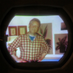
Spent some time this evening on alignment of the color demodulator. Followed the RCA manual for the Chroma AFC, Chroma bandpass, and Color Matrix adjustments. Fortunately I've got an old Sencore color bar generator that generates the I and Q type pattern the RCA manual instructions are based on. Had to spend some time with the Sencore and a modern color set first to get the color bar generator working well enough. After alignment, it looks like this CT-100 can produce some decent looking color.
Purity is not good (see first pic), regardless of adjustment of the cross purity adjustment and field cancellation. Best is with no current in the purity coil (unplugged, or adjustment fully counterclockwise). Would you guys say this needs degaussing, or something else? If it needs degaussing, can the field cancellation coil be drafted into service as a degausser with a variac, or is that coil capable of too little current and field to do the job? (I also don't want to burn it out, of course.) The remaining pics are simply showing that we now have reasonable color. Convergence still has big problems, so that will be a project for another day. Overall, we're getting closer... 
|
|
#82
12-05-2013, 07:52 AM
|
|||
|
|||
|
Great work Tom
 looking good. Not a expert on the CT-100 but I always start with a good degaussing. On sets that have them I start by fully retracting any perm magnets that may be used for edge purity (my CTC-5 had those). then use on of the large old school degaussing rings.
|
|
#83
12-06-2013, 01:51 AM
|
||||
|
||||
|
Thanks to a tip in a PM from one of our friendly VK members, I was able to get the purity much better (see first picture). What I had not yet tried was changing the position of the yoke along the neck of the CRT, and that helped a lot in terms of cleaning up the top edges of the raster for red purity. Now the color rendition is acceptable over the entire screen. The small amount of pink in the upper right corner is not easily noticeable in a normal picture.
I tried using the field cancellation coil as a degausser to see if any further improvement could be made. After all, the cancellation coil does bear some resemblance to the automatic degaussing coils built into newer sets. The wire size looked like it could handle an amp with no problem, so I applied AC current up to 1 amp (about 40 volts AC) and then backed off slowly. This had no effect on purity afterwards. It probably takes a lot more current than what I applied (automatic convergence coils give a nice buzz for the moment they work, and this coil never got into that regime). In any case, I'm not interested in testing the limits of the cancellation coil, since I might damage it, and the purity is actually pretty decent now anyway. Worked on the convergence a bit. Horizontal convergence is working properly, and I was able to get good convergence across the horizontal axis (see second pic). The vertical convergence is not working properly -- adjusting both the vertical convergence amplitude and the vertical convergence shape controls has very little effect on the screen. Also the "smile" when probing at the plate of the convergence amplifier looks possibly inverted. I wonder if I have the phase of the new convergence transformer reversed? There may be some other problem in the vertical convergence circuitry, so I'll look into that further next time I get a chance to work on the set. I also mounted the new convergence transformer inside the housing in which the old transformer was potted, and have positioned the solid state voltage tripler module inside the HV cage (not permanently mounted yet, but it soon will be). Also adjusted the range of the DC convergence control by adding 5 megohms on the top side (for some reason my control is only 10 megohms as opposed to the 15 megohms on the schematic; adding this resistor get the sweet spot properly within the range of the control). I also made a slight modification to the focus control circuit. I'm still having loss of focus on very light or white screens. There isn't any evidence that this is caused by loss of regulation of the HV, so I think it is the focus voltage that is sagging or otherwise changing in high brightness scenes. I adjusted the range of the control (it is only 1 megohm as opposed to the 5 megohms on the schematic, so its range is really limited) and also increased the resistive load on the focus rectifier to both improve regulation and pull the voltage down into a range where good focus in properly centered in the range of the control. This may have improved focus stability, but I am not sure yet. It still won't stay in focus on the very brightest scenes. Nonetheless, it is watchable at this point.
|
|
#84
12-06-2013, 08:48 AM
|
|||
|
|||
|
"Oh the tenacity!" Seriously, I am envious (not jealous) and very happy to be able to follow this thread. So very few of these sets out there. My only "roundie" is a CTC-9 that is in the queue. I only hope that I can be as persistent and have good results.
Thanks for taking the time to do the work and share it with us.
|
|
#85
12-06-2013, 05:01 PM
|
||||
|
||||
|
Here is a tip on how to obtain a cheap degaussing coil if you ever feel the need to have one. Step one: Find a 'modern' CRT set on the curb or grab a 1$ thrift store special. Step two: Remove the internal degauss coil from it (sets with screens over 20' tend to have good degauss coils that can handle line voltage for a few minutes). Step three loop the coil into a ~16" ring, wrap that ring with electrical tape, and connect a line cord to the leads of the coil (make sure the cord is over 7' long if you do not want to use extension cords). Step four: test it out. If it does not get too hot to hold in ~4-9 minutes it should be good enough to get the job done.
__________________
Tom C. Zenith: The quality stays in EVEN after the name falls off! What I want. --> http://www.videokarma.org/showpost.p...62&postcount=4
|
| Audiokarma |
|
#86
12-06-2013, 05:19 PM
|
||||
|
||||
|
Great idea, Tom. I would suggest adding a series on/off thumb operated switch in series with the AC line, as it is useful to be able to turn the coil on and off with the flick of a finger.
__________________
John Folsom
|
|
#87
12-06-2013, 05:21 PM
|
||||
|
||||
|
Quote:
-Steve D.
__________________
Please visit my CT-100, CTC-5, vintage color tv site: http://www.wtv-zone.com/Stevetek/
|
|
#88
12-07-2013, 12:40 AM
|
||||
|
||||
|
Thanks for the tips on the degaussing coil. I checked eBay a few days ago, and only saw one for $39, which I thought was perhaps a little steep. Buyers for degaussing coils these days are probably few and far between! Anyway, there is certainly a nice selection of degaussing coils today, so I decided to order one.
I've parted out a few color sets over the years, and have always pulled the degaussing coils as a very useful source for a lot of nice magnet and coil wire in a very accessible form. I may have one of those fully intact somewhere, but I guess it will be nice to get one of the commercial degaussing coils instead of trying to make use of an old coil from a junked color set. Certainly sounds workable enough, though. I've been making some measurements of what's happening when the focus goes out on bright scenes. I'm becoming convinced that the problem is focus voltage instability, not a HV regulation problem. The HV hardly budges, while the focus voltage changes by several hundred volts out of about 2.5 kV. Does anyone know of a solid state replacement for the 1X2B? I may also try a string of a bunch of 1N4007s just to see if a lower impedance rectifier would make much difference. I suppose I should check whether the voltage at the output of the 1X2B (as opposed to at the focus output to the CRT) is stable before worrying about the rectifier itself. It's possible that the voltage dropping potentiometer and resistors are the problem, driven by a change in current on the focus grid. The circuit looks like it was designed with the assumption that the focus grid would have little or no current flow, but I certainly seem to have enough to cause a problem. I've been hearing from some of you that defocusing on bright scenes is par for the course on these sets, so this experimentation with focus stability is perhaps really more about understanding the design limitations of the set, and not true restoration, I suppose. I'm also wondering if there is just a touch of gas in my CRT, which may be having some subtle effects. Still working on the vertical dynamic convergence -- that remains one trouble spot with the set. It's watchable, but would be nicer at the bottom of the screen with better dynamic convergence.
|
|
#89
12-07-2013, 01:35 PM
|
||||
|
||||
|
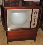
Well, we've gotten far enough along on this that it looks like electrical restoration will be a success, so I guess it's a keeper.
Next I'll work on the cabinet. I won't post a blow-by-blow on the cabinet work, but I thought it would be nice to document the original as-acquired cabinet condition. Pictures attached. Will post some more when the cabinet is done. Last edited by Tom Albrecht; 12-07-2013 at 01:43 PM.
|
|
#90
12-07-2013, 01:36 PM
|
||||
|
||||
|
A few more pics of original condition. Note some damage to the feet on the right side.
|
| Audiokarma |
 |
|
|


 Linear Mode

