
|
|
|
#46
 01-10-2011, 04:25 PM
|
||||
|
||||
|
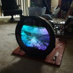
As you can see on the above screenshot, covergence is still horrible and there are bad purity issues. Right now the raster buttons on the NTSC gen have little effect, so I'm thinking it's now time to delve into the demods and figure out why I can't get the chroma part of the chassis to do anything. Once I get that sorted, I should be able do the screen tweaks necessary to get a nice picture up on the tube.
__________________
Evolution... 

|
|
#47
01-10-2011, 10:22 PM
|
||||
|
||||
|
I hope you don't really mean a full chroma bandpass align first. First thing is to make sure the oscillator locks and then that the tint control is centered. And really, before that, why not work on getting the purity at least approximately right, so you can see if the tint looks OK.
|
|
#48
01-10-2011, 11:09 PM
|
||||
|
||||
|
Well, first I have to see if I can get the driver tubes to do the right thing. Otherwise anything in the chroma circuit is pretty useless. I can see right now that the local oscilator does in fact lock, because there are bars that will float by vertically then lock in. It's only visible as a slight change in brightness right now, but it's there. I scoped the burst amp tube a bit ago, and it looks like the burst is gated correctly and getting through to the rest of that section, so at least I have that much going for me. I think for now the right thing to do will be to see if I can somehow get the purity magnets mounted (something like what you had to do to your 5), and sort that out.
Before any of that though, while I was scoping the burst gate (amp, whatever) I smelled ozone coming from the HV cage and heard leakage. Pretty sure I'll have to pause and replace the filament windings for the rectifier tubes before going any farther, so I'm off to scrounge some 40 kv wiring.
__________________
Evolution...
|
|
#49
01-10-2011, 11:11 PM
|
||||
|
||||
|
Oh, I almost forgot: I was perusing Ebay the other day, and found myself an RCA WP-25A Isotap isolation transformer for the pauperly sum of $25. Should make a nice addition to my vintage arsenal of electronic tools. :p
__________________
Evolution...
|
|
#50
01-16-2011, 04:55 PM
|
||||
|
||||
|
Today, I was working on the set and the smell of ozone was in the air. I suspected the old HV wiring in the cage was to blame, so I set about replacing it. I have a slew of newer chassis in the garage thanks to Doug, so I grabbed a spare Sylvania chassis and robbed the wiring from it. The old CTC-4 stuff was cracked in a few places, so I have no doubt there was leakage occurring. It was only single jacket stuff anyway, the new stuff is more modern double jacket.
First I replced the filament winding for the 3A3 rectifier, holding it in place with shrink tubing around the flyback core.
__________________
Evolution...
|
| Audiokarma |
|
#51
01-16-2011, 05:05 PM
|
||||
|
||||
|
Then I tried to replace the wire on the focus rectifier, but it was no use due to the molded cap. I didn't have a spare small size top cap, so I had to carefully remove the one on the tube and solder a bigger one on to it. This involves carefully grabbing the cap with pliers and slightly twisting it, so the old glue will break free of the glass. Then it's simple to desolder the cap, and replace it. I took the replacement one from a dead HO tube, and used epoxy to glue the metal cap onto the top. Then I used a normal size connector, some more replacement wire, and sealed the connection on the flyback with non-acetate RTV. I doubt there will be any leakage from there now.
 Also, for some reason there was a 22K resistor in series with the anode cap lead. I couldn't find it anywhere in the schematic, so it was removed. There seems to be more range in the focus control now, so that's good.
__________________
Evolution...
|
|
#52
01-16-2011, 05:15 PM
|
||||
|
||||
|
Back to the rectifier. Having already replaced the filament wiring, I now soldered that to the socket. That brought me to the wiring under the socket, which connects to the HV capacitor and HV tower on the side of the cage.
I never really liked the way the HV capacitor was connected under the rectifier cup, with an 'X' shaped solder lug. It screwed into the capacitor, then the rectifier cup and HV tower connection soldered to that. This made wire breakage an issue, since to remove the cage means leaving the tower flapping in the breeze. So I made a short wire with round terminals on each end: one screws into the cap, the other end goes to the top of the rectifier cup. This does 3 things for me: 1. I can pull the rectifier cup and the cap doesn't fall out now, because there's still a screw and a lug holding it in. 2. It also allows me to remove only the cap if I choose, since I can put a phillips screwdriver down the center of the tube socket (no need to pull the cup if I just want the cap out). 3. the HV wiring is now modular. The HV tower can be disconnected from the rectifier cup, so the tower and shunt reg cap all come off in one piece. Very neat now, and I no longer have to pull the cover of the cage to get the cage off the chassis. I simply remove 1 screw from the rectifier cup, and the whole cage comes out in one piece. The pics below show what it looks like now. 
__________________
Evolution...
|
|
#53
01-16-2011, 05:30 PM
|
||||
|
||||
|
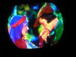
And now, for the grand finale!
After a few tweaks to the demod driver transformer, we now have color bars!  Purity and convergence are still a mess, but this proves that 99% of the parts in the chassis are doing what they are supposed to do. That makes me very happy indeed, since this thing was a basket case of prior hacks when I first picked it up. Twice rebuilt picture tube, melted insulation, frazzled video peaking coil, bad solder joints, and more incorrect connections than I can count on both hands... Along the way, I also found that whoever replaced the flyback had mistakenly swapped terminals U2 and U3, which supply pulses to the blanker and burst keyer tubes. Not sure how much difference it makes since the voltage difference in the actual pulses is small (50 volts), but I fixed it anyway for the sake of correctness.
__________________
Evolution...
|
|
#54
01-16-2011, 10:54 PM
|
||||
|
||||
|
Congratulations - but your dancing bananas are purer than your color bars

|
|
#55
01-17-2011, 12:32 AM
|
||||
|
||||
|
That set is looking nice already. Keep up the good work.
__________________
Chris Quote from another forum: "(Antique TV collecting) always seemed to me to be a fringe hobby that only weirdos did."
|
| Audiokarma |
|
#57
01-22-2011, 03:05 AM
|
||||
|
||||
|
Did more work the other day, and discovered that I would never get correct purity without the correction magnets- this CRT has a large area of impurity in the lower left hand side. So I installed the magnet assembly around the CRT, and tweaked it best as I could. Result is below, how's it look now Wayne?
__________________
Evolution...
|
|
#58
01-22-2011, 01:39 PM
|
||||
|
||||
|
Quote:

|
|
#60
01-22-2011, 06:55 PM
|
||||
|
||||
|
That looks really nice! Mine has a very small purity problem in the lower right corner, and I think it might be due to the tube needing to be degaussed, but I'll try the magnet again. The rest of the screen is just right.
BTW, I notice that your 4 also doesn't fill the screen all the time at the left side. Interesting; mine does the same thing. If I increase the line volts to 120 I can get a full pic. These things have notoriously poor voltage regulation, so maybe that's one of the problems. Don't want to screw around with the width circuit again yet. Kevin
__________________
stromberg6
|
| Audiokarma |
 |
|
|


 Linear Mode

