
|
|
|
#33
 12-10-2010, 10:00 AM
|
|||
|
|||
|
Seems perfectly happy at 110v still holding at 23-24kv with reg current down to about .9ma, HOT current dropped to just under 200ma at the reduce voltage.
That was with the shunt grid resistor jumped, without it, the max HV was 19k and the shunt tube was 1.3ma at the reduced line voltage. I hope to pull the chassis sometime in the next few days to do a proper check/fix of that and also check/replace any other faulty caps (like that video amp cathode bypass cap. Just trying to decide best way to pull the chassis, will have to make notes of lead dress etc... as there are wires all over the place, tied back to various points, a lot using the CRT mounting for tie points. Last edited by DaveWM; 12-10-2010 at 10:20 AM. 
|
|
#34
12-10-2010, 11:10 AM
|
|||
|
|||
|
almost got it out, not as bad as is it seems, the UHF has the power switch and most of the hard wiring back to the chassis, I can leave the VHF in place and just disconnect the IF, AGC, B+ and filament leads. Have one less piece of stuff dangling. I am sure there is a way to mount the UHF and all the pots to the main chassis, maybe that will become obvious once I pull it back.
|
|
#35
12-10-2010, 12:09 PM
|
|||
|
|||
|
whew that was fun, its out now, that pesky 1.5 was reading 2.2 and its a 5% so I guess that was the problem after all. going to be testing cans, but my guess is they will all need to be replaced. On stuff I dont care about how the cans look, I generally just bone saw off the can and stick radial caps down from the top, that is the fastest way and keeps all the lead dress untouched.
Since no one will be seeing it anyway I generally do not bother to put the can back on top. effectively the can bottom acts like a term strip with the caps mounted on the top.
|
| Audiokarma |
|
#37
12-10-2010, 05:35 PM
|
|||
|
|||
|
generally yes the doublers have the cardboard, and I do exactly that when I have extra covers.
So far the 1st can 4/4/100/200uf 475/475/475/50v only the 100uf 50v was open, the rest test like new. For now I am just going to bridge the 100uf and finish checking the rest. I am bit short on my 450v caps, so the plan will be to check the remaing cans, and see if I can get it going, then I can make up an order and get the proper caps.
|
|
#38
12-11-2010, 12:08 AM
|
|||
|
|||
|
well every other can cap tested fine, oh well nver hurts to check. I have checked all the brightness stuff since the CRT was a bit dim, all looks good. So to recap no pun intended,
200mfd 50v cap on video amp tube. 1.5 meg resistor on shunt tube. I cleaned up the pot controls, including the on off volume that was inside the uhf knob it was sticky. I sure hope there is no diddliing needed, the coil forms have what looks like dried cheese in them, my guess is the forms have started to break down. I will put it all back together tomorrow, set it on the variac (to keep the HOT current low, use 110v ac line) and do a complete setup. hmm the only thing I did not check was some of the caps on the convergence board, there was a bumble bee in there as well as one of white tube caps. I will check that out as well, my guess is the bumble bee will be leaky. Anyone have exp with the yokes with the fishing line coming out of them? from what I read there are for centering the pic, but I have never had a set with them.
|
|
#39
12-11-2010, 10:50 AM
|
||||
|
||||
|
Quote:
__________________
Evolution... 
|
|
#40
12-11-2010, 01:11 PM
|
|||
|
|||
|
Sense the crt is weak this would be a good candidate to increase the HOT screen resistor. Right now you just got a lot of HO wattage being wasted in the shunt tube because the crt cant use it.
It would be a good set to experiment on. You should be able to get the cathode down around 200ma or lower at line voltage and not see a performance change.
|
| Audiokarma |
|
#42
12-11-2010, 07:48 PM
|
|||
|
|||
|
drilled the rivuts, pulled the back off, careful not to let the other pin sockets come loose. the old focus connector remants were completely corroded, fell apart as I pulled it out. I was able to find a connector at rat shack of all places...
got it all back together used some small allen machine screws to hold it togehter. I will put it back in the cabinet tomorrow and see where we are, I am always a bit concerned after pulling a chassis that I have upset wiring under the chassis, so I try to be extra careful how I handle it so as not to push some part into another.
|
|
#43
12-12-2010, 02:03 PM
|
|||
|
|||
|
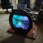
got it back in the set. Aftef fiddling with it forever I finally got it working again, a color amp tube is very touchy, I will need to clean the pins it took a lot of messing about, but looking pretty good. You can see the blue gun blooming so I will try some more setup. Plus the yoke is a tad crooked, so I will go back and straighten it out, but its not bad, def watchable. I just hope at some point CRT rebuilding become avail again. I think if the CRT was strong it would look great. I will snap some pics later after I get the yoke done and get the chassis all back togehter.
|
 |
| Thread Tools | |
| Display Modes | |
|
|


 Linear Mode

