
|
|
|
#1
 12-08-2020, 11:23 PM
|
||||
|
||||
|
RM-503 oscilloscope TV project
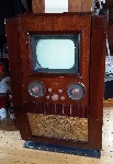
Well, since my last GE clone project seems to be winding down, and I would be needing something else to play with, I thought about what else I could tinker with, I already have 3 color sets, 2 vintage tube ones, and the one I hate, the CTC-90, and 2 vintage BW sets, the FADA and the Stromberg Carlson, so I thought it's time for another BW set.
But finding one is not so easy, but then I remembered the site I saw about a converter for using an oscilloscope as a TV, and I thought why not? I have not played with static deflection TV before, and I did have the RM-503 that has been sitting for years collecting dust. Stock pictures. http://w140.com/tekwiki/images/6/68/RM503_5.JPG http://w140.com/tekwiki/images/a/a7/RM503_bottom.jpg http://w140.com/tekwiki/images/f/f2/RM503_1.JPG how to do it. http://www.electronixandmore.com/pro...ope/index.html A brief history of the unit, I saved it from certain destruction while working at my first job as a tech in the mid 90s, I noticed it and asked about it, It did not work,sort of, and asked and they let me have it, it would have been scrapped otherwise, when I tried it then, it DID come on but barely worked, and would not make a usable trace on the screen, but if you messed with it you could see the scan run across. Since then, it has sat all these years in storage, until last week when I tried to slowly bring it up, and the main power tube exploded, in a nice purple glow and pretty sparks, and looked like this inside. https://i.imgur.com/TOjlwoF.jpg there was also a warm cap, not TOO hot, this was not the cause of the tube going south, it was gassy. I'm sure. https://i.imgur.com/Ry1UQ1Z.png https://i.imgur.com/xISiHy0.png C654 was getting a bit warm so I'm replacing it. all others were cold V620 exploded new one coming. This thing is VERY well made, only 4 paper caps in the unit, surprising for something this old, and they are in places that do not matter, ALL others are ceramic or mica,etc, save for the electrolytic capacitors in the PWS. once I get the new power tube and the cap in I will try to power it up again, I don't expect it to fully work yet, but I don't expect it to blow up again! 
__________________
=^-^= Yasashii yoru ni hitori utau uta. Asu wa kimi to utaou. Yume no tsubasa ni notte. いとおしい人のために 
|
|
#2
12-09-2020, 07:40 PM
|
||||
|
||||
|
What really blew my mind about this scope, is that they gave extra solder with it, in a spool stuck to the underside, they had THAT much forethought, you don't see stuff like that anymore, do ya?
__________________
=^-^= Yasashii yoru ni hitori utau uta. Asu wa kimi to utaou. Yume no tsubasa ni notte. いとおしい人のために
|
|
#3
12-09-2020, 10:04 PM
|
||||
|
||||
|
I believe they used a special solder alloy containing silver for those ceramic terminal strips. Regular solder does not work very well if you need to to repairs.
|
|
#4
12-10-2020, 12:39 AM
|
||||
|
||||
|
Ah yes, that o-scope tv conversion thing. I dug that up years ago, when I was trying to make a simple standalone crt driver. I have all the parts, still, scattered around here somewhere. Not that they're expensive or anything. I seem to recall that it barely worked on either of my scopes. That might be down to my scopes not being terribly sensitive, though. I think you need it to be pretty fast.
|
|
#5
12-10-2020, 09:13 AM
|
||||
|
||||
|
Quote:
|
| Audiokarma |
|
#6
12-10-2020, 08:00 PM
|
||||
|
||||
|
CAP rebuilt
https://i.imgur.com/xl7SATP.jpg https://i.imgur.com/mCg7Nnt.jpg now I wait for the new tube.
__________________
=^-^= Yasashii yoru ni hitori utau uta. Asu wa kimi to utaou. Yume no tsubasa ni notte. いとおしい人のために
|
|
#8
12-10-2020, 11:27 PM
|
||||
|
||||
|
Quote:
if you look at the schematic posted above, there is no way to get a good resistance/ diode check on the 12v line with them in, so to make sure d672 and all after was OK, i took them out, otherwise there would be about 10 ohms to gnd on the line.
__________________
=^-^= Yasashii yoru ni hitori utau uta. Asu wa kimi to utaou. Yume no tsubasa ni notte. いとおしい人のために
|
|
#9
12-12-2020, 03:25 PM
|
||||
|
||||
|
Well STILL no new tube,,
It's stuck in limbo, THANK YOU USPS... Not to get all political or anything, but they really have gone to crap this year, and I hope the can get things fixed with the new year. OH SURE, they would love to blame it all on the season rush, and the pandemic, and staffing, blah blah blah, but it does not stand up to logic when an item shipped from GREAT FALLS, VA 22066 on 12/7/2020 gets to an Austin TX PO on 12/10/2020 with an expect delivery date of 12/11. and then STOPS moving. It is obvious something has gone wrong. From 2am 12/10/ to 3;30 12/12 no scan? WTF?
__________________
=^-^= Yasashii yoru ni hitori utau uta. Asu wa kimi to utaou. Yume no tsubasa ni notte. いとおしい人のために
|
|
#10
12-14-2020, 07:51 PM
|
||||
|
||||
|
I got the power tube today, finally which i put in and tried, and it did NOT blow up!
 but I got no power from it I had to remove to 6LB8 to get it to do anything at at all, so it may too be bad/ damaged. I was NOT expecting this to be easy! but I did see SOMETHING on the CRT... https://i.imgur.com/yIbPpfT.jpg 
__________________
=^-^= Yasashii yoru ni hitori utau uta. Asu wa kimi to utaou. Yume no tsubasa ni notte. いとおしい人のために
|
| Audiokarma |
|
#11
12-14-2020, 10:29 PM
|
||||
|
||||
|
I will most likely have to replace more parts in the PWS, cause it just does not want to self oscillate.
As mentioned, it did not explode anymore, but it tends not to want to free run like it should.
__________________
=^-^= Yasashii yoru ni hitori utau uta. Asu wa kimi to utaou. Yume no tsubasa ni notte. いとおしい人のために
|
|
#12
01-13-2021, 07:15 PM
|
||||
|
||||
|
still have not given up on this little project!
 but due to my shoulder surgery on 12/24, i have not had much time to put into it, due to all the downtime with recovery and PT, not to mention the cost of everything,  does not leave much extra for new parts. does not leave much extra for new parts.It STILL wont power up half the time, IE the main PWS won't self oscillate, it i a very simple circuit, scans above, but when it messes up, it is a REAL DOG! so far, only C654 and V620 have been replaced, and the few times I HAVE been able to get it to start and free run correctly, I was able to get a bright focused dot on the CRT, but it did not last long, a 60 - 90 seconds before the circuit collapsed on itself and lost power. once I get $$$ to invest into it, I will replace all the other electrolytic caps, and V634, and check all related resistors, ( i doubt any are bad ) and see how it behaves . ALL other Caps are ceramic, and are not suspect.
__________________
=^-^= Yasashii yoru ni hitori utau uta. Asu wa kimi to utaou. Yume no tsubasa ni notte. いとおしい人のために
|
|
#13
01-14-2021, 02:05 PM
|
||||
|
||||
|
Because of the way that circuit regulates it's not going to be very happy being brought up slowly on a variac. It needs to have the expected line voltage within a window in order to lock in oscillating. You pretty much need to make sure the filter caps on all the outputs of T602's secondaries are good. The oscillator circuit relies on the -100 volt supply and 85v reference in order to regulate all the secondary voltages proportionally. It's a feedback loop intended to shut down all the secondary supplies if it's not getting the correct reference voltages.
Last edited by Kevin Kuehn; 01-14-2021 at 02:23 PM.
|
|
#14
01-14-2021, 09:11 PM
|
||||
|
||||
|
Quote:
__________________
=^-^= Yasashii yoru ni hitori utau uta. Asu wa kimi to utaou. Yume no tsubasa ni notte. いとおしい人のために
|
 |
|
|


 Linear Mode

