
|
|
|
#16
 01-10-2019, 08:25 PM
|
||||
|
||||
|
Quote:


|
|
#17
01-11-2019, 05:02 AM
|
||||
|
||||
|
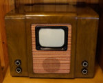
It sounds strange that the HV cage had to be cutted while replacing the CRT. The metal cone of the 'old' CRT was supposed to be pretty far from any metal parts to prevent arcing. Is the glass CRT that much bigger than the metal/glass one?
Good luck in restoration of such a wonderful television!
__________________
To understand a bygone era, you should use things from it Last edited by Gleb; 01-11-2019 at 07:12 AM.
|
|
#18
01-13-2019, 06:02 PM
|
|||
|
|||
|
Quote:
I'll post a picture later. Here's the picture: I suppose that this was because of the metal tube and a HV cover could still be used. 
Last edited by Crist Rigott; 01-13-2019 at 06:07 PM.
|
|
#19
01-13-2019, 06:09 PM
|
|||
|
|||
|
As my usual practice, I labeled all the components. I also ran to Mouser and picked up the parts that I needed like E-Caps and some resistors.

|
|
#20
01-13-2019, 07:41 PM
|
||||
|
||||
|
Quote:
The metal tube would place the screen right at the edge of the flare, but the glass would place the screen 1-3" out from that and leave a flat side around the screen where a mounting strap could be placed... Despite many metal glass pairs having basically the same socket to screen dimension, the rear shifted bell meant a shorter neck and repositioning of the yoke...If you've ever converted an American metal CRT set to a glass CRT you probably will have had some fun mounting hardware modifications to do.
__________________
Tom C. Zenith: The quality stays in EVEN after the name falls off! What I want. --> http://www.videokarma.org/showpost.p...62&postcount=4
|
| Audiokarma |
|
#21
01-14-2019, 11:10 PM
|
|||
|
|||
|
I re-stuffed the electrolytic caps in my usual way. This time I used all Nichicon 10K hour 105C caps.
C3 consisted of a 47uf 450V and a 4.7uf 450V caps. They were the same diameter and I used a pieces of heat shrink to connect them together instead of hot glue. I left a small gap between the two in case one vents. I used a large pin to poke several holes through the heat shrink tubing.  Next was C4 which had 4 caps. I used a 68uf 450V, 2 27uf 450V, and a 100uf 160V.  Then onto C1 which had 4 caps. I used 47uf 450V, 56uf 450V, 4.7ud 450V, and a 22uf 100V.   C3 was only 1 cap and I used a 3300 35V cap. Top view of C1.  Top view of C2.  Top view of C3.  Top view of C4.  All four ready to install into the chassis. Note that C4 has its can go all the way to the base of the cap. This is the only cap of the 4 that is not insulated from the chassis, hence no paper tube cover. 
|
|
#22
01-15-2019, 07:53 AM
|
||||
|
||||
|
Quote:
 I remember that I hadn't faced any difficulties with replacement a few years ago. I only had to rework the HV supply gear, and change the socket. The cone of the glass tube is just more plumpy but its height is the same, so it fits the original hardware pretty well:  Maybe, the difference is in that my glass CRT is the official replacement for the metal-glass one. What was about American glass CRTs? Were some of them designed as the direct substitutes for obsolete metal tubes, or were they all just newer tubes which had to be used as replacements? Crist Rigott, you're making good progress on the restoration! Hope to see a picture on the screen soon!
__________________
To understand a bygone era, you should use things from it Last edited by Gleb; 01-15-2019 at 12:30 PM.
|
|
#23
01-15-2019, 10:03 AM
|
||||
|
||||
|
Quote:
Here in the US metal tubes were only popular in monochrome sets from around 1950 to around 1953.... color CRTs were in development during that time and the metal ones lent themselves best to installation of the shadow mask so when color was standardized in 1953 and into around 1956 (though some Motorola's stuck with metal into the early 60's) metal color tubes were made. The metal tubes seem more prone to leak and fill with air... Even tubes with just a metal evacuation stem are more prone than ones with glass evacuation stems.
__________________
Tom C. Zenith: The quality stays in EVEN after the name falls off! What I want. --> http://www.videokarma.org/showpost.p...62&postcount=4
|
|
#24
01-15-2019, 10:21 AM
|
||||
|
||||
|
Electronic M, thanks for the information!
Quote:
__________________
To understand a bygone era, you should use things from it
|
|
#25
01-15-2019, 11:08 PM
|
|||
|
|||
|
I installed the E-Caps today. Not much to look at in the pictures but I included them anyway. Then I started on the Vertical section. I'll post what I did tomorrow.
 
|
| Audiokarma |
|
#26
01-19-2019, 07:51 PM
|
|||
|
|||
|
It's been a couple of days. I had a few things around the house to get done and I also had to make another round of PC boards for my Network sales.
I finished the Vertical section this evening. The Vertical section contained a couplate or network! While I was going to make some more Network PC boards I drew up one for the Vertical Integrator network. It consisted of 3 resistors and 3 caps. Simple. I first checked the original and it has 3 resistors between leads 2 and 3 that should add up to 38.4K. These measured out to 48.1K. A 25% difference. This one has to go! Some before and after pictures. If you look closely you can see the brown Network under the right hand side terminal strip.   
|
|
#27
01-20-2019, 10:25 PM
|
|||
|
|||
|
I've moved onto the main section of the chassis. I thought I'd start at the top left and work my way across to the lower right.
On the right side of the two terminal strips were 3 27K 2W resistors twisted in parallel. I have 3 27K 3W resistors ready to go back in. But thought I'd replaced the 3 with 1 9K 10W wire wound resistor. What do you think? Some before and after pics.   Then on to another section. The lower capacitor is connected to the left hand terminal of the capacitor above it. When I installed its replacement, I jumpered the lower 2 terminals and installed the lower capacitor on its own terminal.  
Last edited by Crist Rigott; 01-20-2019 at 10:28 PM.
|
|
#29
01-21-2019, 09:20 AM
|
|||
|
|||
|
Quote:
|
|
#30
01-21-2019, 11:43 AM
|
||||
|
||||
|
About installing a 10W wire-wound for the group of three carbon, I would check the schematic to see how that resistor is used. The WW of course has a bit of inductance, so if it is used as a plate load in the video amp it could effect the flatness of the bandwidth. I've seen high wattage carbons used this way. Another place you don't want a WW is in the RF and IF circuits.
|
| Audiokarma |
 |
|
|


 Linear Mode

