
|
|
|
#1
 01-21-2014, 01:56 PM
|
|||
|
|||
|
GE 810 oddness
http://www.youtube.com/watch?v=SxzEV...CVtyRrqXVtll-g
well its such a mess seems like a mod was done, but not sure if it was correct to the HV, fly does not seem orig nor does it match the riders. today I cut the lead that feeds b+ to the horz osc plate and the screen of the CRT and connected back to the boost (this is the way it is in the riders). I left the screen supply for the 6BG6 as is (3 27k resistors in P to the B+). It seems like the set has some changes but not all. The boost is about 450v vs the 370v from the B+. Before this change the HV was about 8kv, width was marginal, and screen brightness required max setting. The CRT bias voltages are correct, just a low G2 due to the use of B+ rather than boost. anyway that single change (boost to horz osc thru the 82k plate load resistor) resulted in about 9.5kv hv and brighter screen. I figured the improvement in brightness due to the higher CRT G2 but was suprised by the higher HV. the grid drive shot up from -9v to about -13v (did not scope PP just looked at the DC reading with a DMM). there are so many inconsistenties between the riders, sams and what was done to this set that its hard to tell what is correct. I am tempted to just re wire the entire HV and Osc to match the later sams that has a fly that seems consistent with what is in there (secondary with 4 leads). figure a fly change was done at some time and maybe not all the fixes were put into play. the riders mentions a newer fly as a production change, but the work does not look very factory, maybe a replacement fly was done by a tech that did some short cuts. 
|
|
#2
01-21-2014, 02:15 PM
|
||||
|
||||
|
I have two 810 chassis and both flybacks look like this.
|
|
#3
01-21-2014, 02:27 PM
|
|||
|
|||
|
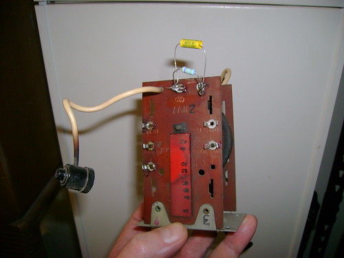
thats the one I have bob, but for the core is 1/2 black and 1/2 red, the term plate is the same. See if you have a 82k or 47k plate load resistor (goes to red lead of horz osc transformer mounted on a term strip same one used for the horz out screen resistors.
My guess is the 47k is used when using B+ while the 82k is used when boost is used. Would be nice if could find the prod change sheet refereced in the riders detailing ALL the changes needed to change the fly's.
|
|
#4
01-21-2014, 02:33 PM
|
||||
|
||||
|
That looks depressingly familiar. That 814 I picked up a few weeks ago has that flyback. Apparently somebody tried to use it as a replacement and started to rewire the HV cage like an 810...sort of. It's a mess.
Sorry, don't mean to derail. Actually, you're welcome to my flyback if you can hook my up with one I can use.
__________________
tvontheporch.com
|
|
#5
01-21-2014, 03:14 PM
|
||||
|
||||
|
I have an 82K plate load resistor. There's some info about this flyback in the Riders service notes. It would be nice to find a copy of those step-by-step instructions that came with them.
Here's my youtube video where I muddle my way through the flyback connections: http://youtu.be/8Eq2KpqRGZ0?t=5m32s 
Last edited by bandersen; 01-21-2014 at 03:18 PM.
|
| Audiokarma |
|
#6
01-21-2014, 03:34 PM
|
|||
|
|||
|
I am uploading a video of close ups of mine. curious if you have boost voltage or B+ at that resistor. switching to boost picked up about 1kv at the CRT anode and helped with the brighness G2 voltage. I will go back and watch your video now. Mine will prob be ready in about 30 min depending on upload time. I will post a link when its there.
|
|
#7
01-21-2014, 04:23 PM
|
|||
|
|||
|
|
|
#8
01-21-2014, 04:38 PM
|
|||
|
|||
|
one more demo of the diff in boost drive vs B+ to the horz osc and effect on HV. because of the way the set is wired the G2 on the CRT gets what ever the plate load resistor for the horz osc gets as well so the brightness increases is prob more do to the G2 than the HV but I am sure the extra HV does help brightness as well.
http://www.youtube.com/watch?v=dEiGWFisXMA
|
|
#9
01-21-2014, 04:51 PM
|
||||
|
||||
|
The 82K resistor is going to boost in my set.
|
|
#11
01-21-2014, 08:28 PM
|
||||
|
||||
|
Quote:
__________________
Tim
|
 |
|
|


 Linear Mode

