
|
|
|
#1
 05-28-2022, 01:28 AM
|
|||
|
|||
|
Blonder Tongue Question
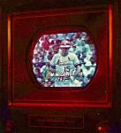
I picked up a second BT modulator, a CAMD 60a, “channelized agile modulator”. It turns out it’s not like the one I’m already using, from the AP series that has front dip switches for Channel in and out. The one I picked up seems to only have a channel out setting using two dip switches inside, accessible from a removable panel on the top of the unit.
It would appear there’s no way to set the input channel (frequency). Internally the dips cover output to channels 7-13 and 23,24 and 25. Since I don’t have a manual I’m not understanding how to configure it so that an input from my set top box, say channel 3 or 4 is broadcast at a channel of my choice from above. NOTE I am using a jumper for the IF loop, not shown in the picture.     Above pic shows the channel output module and dips. Again I don’t know what kind of input this unit is looking for. Perhaps it only takes an input channel that matches the output? But that would defeat the purpose of an agile device… Last edited by Jon1967us; 05-28-2022 at 04:06 AM. 
|
|
#2
05-28-2022, 08:58 AM
|
||||
|
||||
|
First off "Blonder Tongue" is a company, it made many products over the years, antennas, UHF convertors, antenna amplifiers, etc.
All the agile modulators I know of use the baseband video (component video) as an input, none of them use an RF channel as an input. You can use a RCA to F adapter on the video input. The sound is a separate input. If the sound input has a RCA input you don't show it in your pictures. You might need to rig a RCA to separate wires adapter for the terminal strip. Note that excessive signal level can cause problems.
|
|
#3
05-28-2022, 09:36 PM
|
|||
|
|||
|
Well, I tried to use the composite out of my Leader pattern generator and fed it into the Video In F connector on the Leader and still no signal broadcast on the output channel i have selected on the BT. It went from a bnc on the Leader out to clip on the center conductor and shield of a Coax cable that’s connected to that video in.
|
|
#4
05-29-2022, 06:49 AM
|
|||
|
|||
|
I would say that IS a modulator. Some modulators I have seen use an F connector for video input (wierd). A processor goes from channel in to channel out. For CATV systems it is important to convert local channels to another channel to avoid co-channeling problems.
BUT, in pict 4 it says OFM750HB. The HB tells me its a High Band unit (Channels 7-13). Its very likely you have a component failure in the unit. From what I remember from my CATV days, the mixer diodes fail due to lightning strikes nearby.
__________________

|
|
#5
05-29-2022, 10:54 PM
|
|||
|
|||
|
Quote:
|
| Audiokarma |
|
#6
05-30-2022, 02:42 AM
|
||||
|
||||
|
F connectors are used for video input on all the B-T Pro units so that the installers only need to deal with one type of connector, cable, and crimping tools. Makes the installation more efficient.
Channelized usually means that it is designed to work with a module that only handles one channel, if you need a different channel, you get a different output module and configure the unit for that channel.
__________________
Tim
|
|
#7
05-30-2022, 12:35 PM
|
||||
|
||||
|
Quote:
 jr
|
|
#8
05-31-2022, 08:42 AM
|
||||
|
||||
|
Yeah the diagram is upside down compared to the switch ID.
Check the dip switch settings. That may be a good catch! Last edited by Notimetolooz; 05-31-2022 at 08:46 AM.
|
 |
|
|


 Linear Mode

