
|
|
|
#16
 06-22-2019, 01:29 PM
|
||||
|
||||
|
Quote:


|
|
#17
06-22-2019, 02:08 PM
|
||||
|
||||
|
Quote:
Maybe, but probably not. I did the steps I reported in the sequence listed. I started to have success with #3.
|
|
#18
06-23-2019, 10:33 AM
|
||||
|
||||
|
Over in the ARF the subject of the H.V. transformer has recently come up.
https://antiqueradios.com/forums/vie...p?f=3&t=359879
|
|
#19
06-24-2019, 08:22 PM
|
||||
|
||||
|
The bottom of my HV Coil assembly has a resistor on Pins 5 and 6. It doesn't show up on the schematics that I'm looking at (late production 6AU6 T-54) and I can barely read the bands. I THINK it's Green-Black-Yellow. 500 kohms. Half watt.
It tests OL on my Fluke. The 6C4 oscillator is such a critical tube so I want to get it right. My HV Coil board has two .25uF 600V and one .001 6kV. Any ideas, Gents?
|
|
#20
06-24-2019, 08:38 PM
|
||||
|
||||
|
Quote:
|
| Audiokarma |
|
#21
06-25-2019, 01:15 AM
|
||||
|
||||
|
The way I always think about it is the stripe on the diode is the | from the schematic symbol ->|-
Which would also be the opposite of what Tom said, I believe he meant the + comes out of the stripe side. But the stripe side is the cathode (-) and the arrow side is the anode (+). So remember my mnemonic device so you don't get confused: in the symbol ->|- the arrow points in the conventional direction of electricity flow from + to - (not the actual direction in physics, which is backwards O_o [but don't think about that]) and the stripe on the diode is the vertical line |. 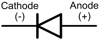 https://learn.sparkfun.com/tutorials...d-led-polarity Last edited by MadMan; 06-25-2019 at 01:21 AM.
|
|
#22
06-25-2019, 05:58 AM
|
||||
|
||||
|
Quote:
Thanks for jumping in. Soooo, the TAIL of the arrow attaches to the lead that was attached to the " + " lead of the Selenium Rectifier? Huh? Oh, Boy. Last edited by M3-SRT8; 06-25-2019 at 06:06 AM.
|
|
#23
06-25-2019, 08:40 AM
|
|||
|
|||
|
Quote:
|
|
#24
06-25-2019, 08:42 AM
|
||||
|
||||
|
Quote:
The stripe on a new diode is the B + end of the selenium. The old selenium polarity notation is bassackwards from modern convention.
__________________
Tom C. Zenith: The quality stays in EVEN after the name falls off! What I want. --> http://www.videokarma.org/showpost.p...62&postcount=4
|
|
#25
06-25-2019, 10:15 AM
|
||||
|
||||
|
Oooookay.
I removed the diode and reattached the leads to the rectifier when I attempted to first power it up. Bringing it up on the Variac yielded nothing. No tubes lit. I checked the switch continuity. It's fine. Checked the leads coming into the switch. They're ok. Did a resistance check on 6X5GT. Strange readings: Pin 1: Inf. Test Inf. Pin 2: 2 ohms Test 1.6 Pin 3: 60k Test soars from 350k Pin 4: Inf. Test Inf. Pin 5: 60k Test soars from 460k Pin 6: Inf. Test Inf. Pin 7: 0 ohm Test 0.2 Pin 8: 70k Test soars past 1 meg What's up with this? Thanks
Last edited by M3-SRT8; 06-25-2019 at 11:13 AM.
|
| Audiokarma |
|
#26
06-25-2019, 12:57 PM
|
||||
|
||||
|
25Z6 Readings. Also way off:
Pin 1: 60k Test Inf Pin 2: 25 ohms Test 144k Pin 3: 160k Test 1.3 meg and climbing Pin 4: 64 ohms Test 144k Pin 5: 10k Test 11.43k Pin 6: 46 ohms Test Inf Pin 7 26 ohms Test 144k Pin 8: 60k Test 1.1 meg and climbing Weird. And the chassis is recapped, and I've checked everything twice, at least.
|
|
#27
06-25-2019, 01:15 PM
|
||||
|
||||
|
Series string set...did you check all of the heaters and assure that tube pins are clean and making connection? 18 ohm resistor ok? All bets are off on the resistance readings until you have heater strings intact.
Also, did you notice that the Sams shows c4a & b connected backwards? that cap actually has common plus ! Riders has it correct. jr
|
|
#28
06-25-2019, 01:38 PM
|
||||
|
||||
|
I already cleaned all the tube sockets with contact cleaner and a pipe cleaner.
I replaced all the 'Lytics as they were wired ex-factory, same grounding points, replaced all wiring with new. Double checked it. Tested all components before install. Tested the tubes before fire up. Would a dead selenium rectifier prevent start up? When I was waiting for an answer on the diode polarity I hooked up the rectifier and attempted to fire it up that way.
|
|
#29
06-25-2019, 01:42 PM
|
||||
|
||||
|
Both 18 ohm resistors near the rectifier test fine.
I had checked all resistors on the chassis before fire up. Replaced only the four 4.7 meg resistors in the sweep section as they were beyond 20%.
|
 |
|
|


 Linear Mode

