Videokarma.org

Go Back   Videokarma.org TV - Video - Vintage Television & Radio Forums > Early B&W and Projection TV

We appreciate your help

in keeping this site going.
Reply
 
Thread Tools Display Modes
  #91  
Old 02-10-2019, 03:43 PM
Crist Rigott Crist Rigott is offline
VideoKarma Member
 
Join Date: Oct 2015
Location: Waxahachie, TX
Posts: 1,506
Quote:
Originally Posted by old_coot88 View Post
Nice! (obviously the det.diode is not backwards).
Thank you.
Reply With Quote
  #92  
Old 02-10-2019, 03:43 PM
Crist Rigott Crist Rigott is offline
VideoKarma Member
 
Join Date: Oct 2015
Location: Waxahachie, TX
Posts: 1,506
Quote:
Originally Posted by electronjohn View Post
Super! (Nice metalwork on the HV cage, too!)
Thank you.
Reply With Quote
  #93  
Old 02-10-2019, 07:18 PM
Tom9589 Tom9589 is offline
VideoKarma Member
 
Join Date: Jan 2013
Location: Stone Mountain, GA
Posts: 472
Isn't it a little odd that they recommend pulling the Horiz Multivibrator tube? Won't lack of horiz drive cause the Horiz Output to red plate?
Reply With Quote
  #94  
Old 02-10-2019, 10:08 PM
Crist Rigott Crist Rigott is offline
VideoKarma Member
 
Join Date: Oct 2015
Location: Waxahachie, TX
Posts: 1,506
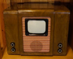
I tackled the yoke and the centering/focus ring tonight. When I took the assembly apart, I found the centering adjustment real rusty.


I then grabbed the one that came in the cabinet and it was rust too but as much. I cleaned it up and reassembled it using some light grease.


Reply With Quote
  #95  
Old 02-10-2019, 10:09 PM
Electronic M's Avatar
Electronic M Electronic M is offline
M is for Memory
 
Join Date: Jan 2011
Location: Pewaukee/Delafield Wi
Posts: 14,790
Quote:
Originally Posted by Crist Rigott View Post
Here is a section of the schematic from Sams. It is R9. Below it are the Alignment instructions that talk about setting the Bias Control. Frankly, how or why its there is above my pay grade.


It is probably an AGC level control. AGC is a feedback circuit that (if keyed) measures the sync pulse amplitude in the video stages (otherwise it just measures average video amplitude over roughly a frame) and varies the gain (via IF and or tuner grid bias) of the IF and or tuner to hold the video level constant...This compensates for differences in signal strength between stations and holds contrast constant in fading signal conditions (such as fringe or DX conditions).....Basically, it makes the contrast control a set and forget adjustment rather than a keep a hand on it at all times and throttle it adjustment.
__________________
Tom C.

Zenith: The quality stays in EVEN after the name falls off!
What I want. --> http://www.videokarma.org/showpost.p...62&postcount=4
Reply With Quote
Audiokarma
  #96  
Old 02-10-2019, 10:20 PM
Crist Rigott Crist Rigott is offline
VideoKarma Member
 
Join Date: Oct 2015
Location: Waxahachie, TX
Posts: 1,506
I then cleaned the yoke and replaced the 3 resistors and 56pf ceramic cap.


Reply With Quote
  #97  
Old 02-11-2019, 02:41 PM
jr_tech's Avatar
jr_tech jr_tech is online now
VideoKarma Member
 
Join Date: Sep 2009
Posts: 4,512
Quote:
Originally Posted by Crist Rigott View Post
Here is a section of the schematic from Sams. It is R9. Below it are the Alignment instructions that talk about setting the Bias Control. Frankly, how or why its there is above my pay grade.


Interesting, thanks for posting! I suspect that they are driving the first two stages of the if amp with a different level of agc (through the dc amplifier, v11) than the rf stage (direct from the local/distant switch) to optimize signal to noise ratio at a given total gain. This is just a WAG.

jr
Reply With Quote
  #98  
Old 02-11-2019, 04:50 PM
old_tv_nut's Avatar
old_tv_nut old_tv_nut is offline
See yourself on Color TV!
 
Join Date: Jul 2004
Location: Rancho Sahuarita
Posts: 7,194
Quote:
Originally Posted by jr_tech View Post
Interesting, thanks for posting! I suspect that they are driving the first two stages of the if amp with a different level of agc (through the dc amplifier, v11) than the rf stage (direct from the local/distant switch) to optimize signal to noise ratio at a given total gain. This is just a WAG.

jr
I haven't traced it through, but if what you surmise is the case, it's quite normal for TV AGC design.

This is called tuner AGC "delay." This doesn't mean a time delay, but that the tuner runs at full gain for weak signals so that the noise figure is maximized [EDIT: I meant minimized, of course]. The tuner AGC gain reduction starts only when the IF AGC gain reduction has already had some effect. In the low signal range (I seem to recall, typically below 1 millivolt RF) the IF AGC is active by itself. Then, above that level, AGC gain reduction is also applied in the tuner.

An alternative, which was never used in TVs as far as I know, is to run both the tuner and IF at max gain for as large a range as possible and use a PIN diode attenuator at the input to adjust signal level.

TVs actually get pretty poor noise figures when the signal is strong and tuner AGC is active, but as long as the video signal-to-noise ratio is great enough to make the noise invisible, it's OK.
__________________
www.bretl.com
Old TV literature, New York World's Fair, and other miscellany

Last edited by old_tv_nut; 02-11-2019 at 05:07 PM.
Reply With Quote
  #99  
Old 02-12-2019, 01:05 PM
Crist Rigott Crist Rigott is offline
VideoKarma Member
 
Join Date: Oct 2015
Location: Waxahachie, TX
Posts: 1,506
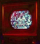
The alignment is done.

Here is what the IF curve should look like.


Here is what the initial curve looked like. Notice that the curve looks good but it is "off" frequency.


Here are the individual points after alignment. Not perfect but pretty close.


Then some pics from this morning.


Reply With Quote
  #100  
Old 02-12-2019, 01:11 PM
old_tv_nut's Avatar
old_tv_nut old_tv_nut is offline
See yourself on Color TV!
 
Join Date: Jul 2004
Location: Rancho Sahuarita
Posts: 7,194
Great!
__________________
www.bretl.com
Old TV literature, New York World's Fair, and other miscellany
Reply With Quote
Audiokarma
  #101  
Old 02-12-2019, 02:02 PM
Gleb's Avatar
Gleb Gleb is offline
VideoKarma Member
 
Join Date: Mar 2015
Location: Russia
Posts: 66
Good job!

What about the equipment you use for alignment? How do you insert the test signal, and couple the detector probe?
__________________
To understand a bygone era, you should use things from it
Reply With Quote
  #102  
Old 02-12-2019, 02:27 PM
Titan1a Titan1a is offline
VideoKarma Member
 
Join Date: Apr 2015
Location: Plattsmouth, NE 68048
Posts: 738
It looks better than new! Really great job!!!
__________________
Rick (Sparks) Ethridge
Reply With Quote
  #103  
Old 02-12-2019, 02:31 PM
Crist Rigott Crist Rigott is offline
VideoKarma Member
 
Join Date: Oct 2015
Location: Waxahachie, TX
Posts: 1,506
Quote:
Originally Posted by Gleb View Post
Good job!

What about the equipment you use for alignment? How do you insert the test signal, and couple the detector probe?
I use an EICO 369 Sweep generator, a BK 200D Signal generator, a Knight KG-625 VTVM, and a BK 2150 scope.

The EICO 369 probe have the Detector in it. I use the probes called out in the EICO manual.
Reply With Quote
  #104  
Old 02-12-2019, 02:31 PM
Crist Rigott Crist Rigott is offline
VideoKarma Member
 
Join Date: Oct 2015
Location: Waxahachie, TX
Posts: 1,506
Quote:
Originally Posted by old_tv_nut View Post
Great!
Thanks.
Reply With Quote
  #105  
Old 02-12-2019, 02:33 PM
Crist Rigott Crist Rigott is offline
VideoKarma Member
 
Join Date: Oct 2015
Location: Waxahachie, TX
Posts: 1,506
Quote:
Originally Posted by Titan1a View Post
It looks better than new! Really great job!!!
Thank you.
Reply With Quote
Audiokarma
Reply


Posting Rules
You may not post new threads
You may not post replies
You may not post attachments
You may not edit your posts

BB code is On
Smilies are On
[IMG] code is On
HTML code is Off

Forum Jump


All times are GMT -5. The time now is 01:38 PM.


Powered by vBulletin® Version 3.8.4
Copyright ©2000 - 2024, Jelsoft Enterprises Ltd.
©Copyright 2012 VideoKarma.org, All rights reserved.