
|
|
|
|
|
#1
 10-16-2018, 02:35 PM
|
||||
|
||||
|
Quote:
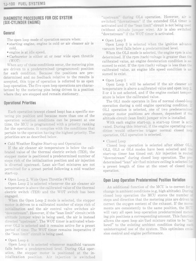
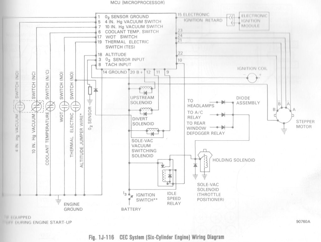
Also coming from people who work with old computers, christ some of these people suck at keeping splices clean and cabling organized. As for the vacuum diagram, this one is pretty close to my engine. Just omit the P/Air solenoids.  On the electronics side, here's some details I pulled when I was researching the purpose of the diagnostic plugs when there should be no actual computer interface in a car this old. It's all just status outputs for the various solenoids, relays and sensors. Coming from my TBI Geo Tracker this type of simple ECU style is really easy to diagnose component faults because the sensors are not running a modern communications protocol and when all else fails, the ECU gives off blink codes and doesn't actually need specialty tools to test. 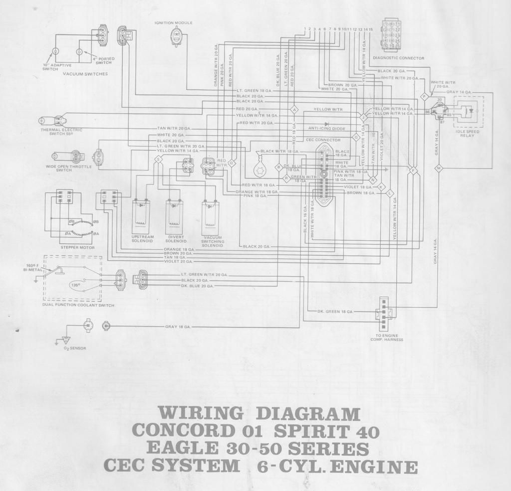 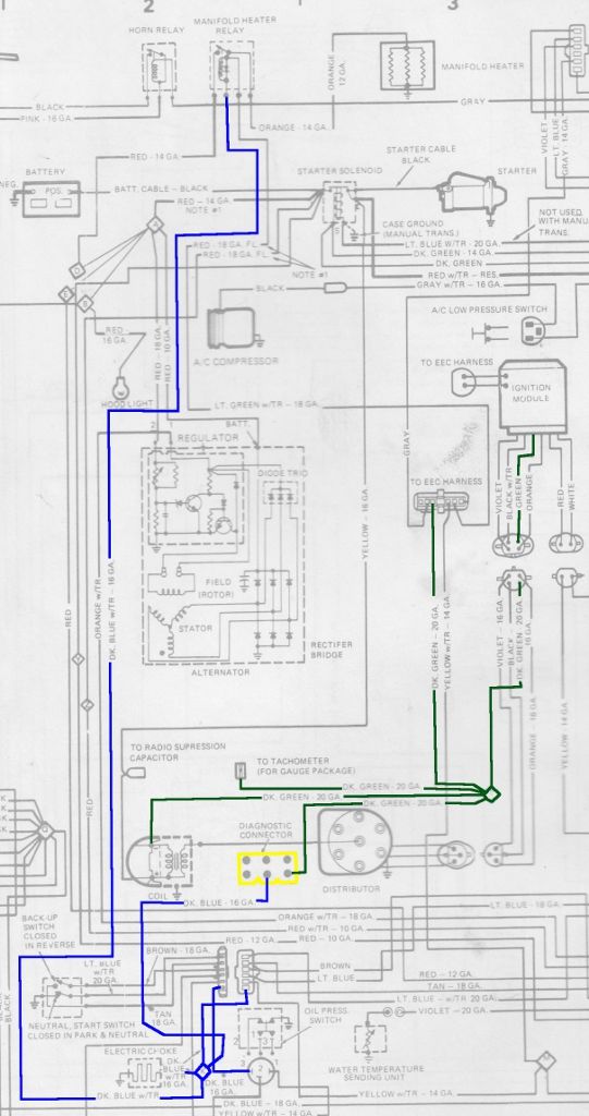 Quote:
I did a very, very quick search on a hunch and the part sells under Carter and Mopar part numbers as well and is relatively cheap. Last edited by MIPS; 10-16-2018 at 04:16 PM. 
|
|
#2
10-16-2018, 01:45 AM
|
||||
|
||||
|
The vacuum solenoid may be for the Idle up actuator which is the solenoid and vacuum item attached to the carburetor.
The electrical part is to set the idle, when you shut the car off it retracts, closes the throttle completely and prevents it from dieseling. The vacuum part kicks in through the vacuum solenoid and idles it up whenever the compressor kicks in, ideally it's adjusted so the idle speed stays the same with the a/c on.
|
|
#3
10-16-2018, 08:44 PM
|
||||
|
||||
|
According to the vac schematic, the cruise actuator is the thing on the center, absolute bottom, called 'VAC. SW. ASM.' Which at first made me think 'vacuum switch assembly,' but who knows what they were thinking - it was the '80s... and AMC. The giveaway, besides having two ports and a noted nearby vacuum reservoir, is that it indicates one port is for 'adapt' and the other for 'idle/decel.' Cruise control terms. That, and there's literally nothing else on the diagram that could be it, lol. Though tbh, I'd have no idea which port is which, without existing vacuum hoses in place. I would assume the bigger diameter would also be the one with the reservoir.
The diagnostic connector is fascinating. It's basically like a datastream that you can check with a test light. Does this car even have a check engine light to count code flashes? I wonder if any of those wires are serial data. Possibly for factory use. Old Fords are like that, the diagnostic connector has a connection to count the pulses with a test light, but then there's a type of serial data that is - quote - 'for assembly line use.' Of course, you can use a scanner to talk to it. I'm gathering from the highlighted wires in the bottom schematic, that the oil pressure switch is responsible for turning on the choke heater (I think that's what the 'electric choke' is) and manifold heater relay. And the other one is the tachometer and coil feed. I'm really confused about the coil though, because it looks like it's only given positive when the starter relay is active O_o Also, I have no idea what the hell the O2 sensor is for. Going by the outputs of the computer, the only realistic thing that it could do is enable the air injection system, which makes sense, it just seems like a waste of an O2 sensor and a computer input. On that 2nd diagram, on the left, there's a 'stepper motor' - which to me, sounds like an Idle Air Control valve - and it's probably that thing on the side of the carb that was unplugged, and has a 6 pin plug. The one in the pic. What gets me is - why does the 'sol-vac' valve exist, if there's an IAC valve? I'd read up on what in the hell the stepper motor is for. Maybe it'll mention something. It'd be awesome if it could change the mixture of the carb in realtime... but I'm just dreamin' here. :P Last edited by MadMan; 10-16-2018 at 09:23 PM.
|
|
#4
10-16-2018, 10:17 PM
|
||||
|
||||
|
You are correct. The cruise control takes a vacuum from a reserve canister and two solenoids in the actuator and the potentiometer control the throttle position. It's described in the magazine link I posted above. It's extremely simple.
The diagnostic plug was used partially for check-out at the factory however regular shop tools including meters and lights can be connected to read back the status of various components and was encouraged for mechanics to use unless you had something like a Sun Modular Engine Analyzer. Those are pretty, but supposedly even the 80's era units still cost thousands. The ECU is too early to have a proper computer interface. Like most cars until the 90's if you want to read out the stored fault codes you gotta use the trouble light. It's pretty bulletproof but I do enjoy how in my Tracker I can at least get realtime engine data without the need for an expensive external system*. For AMC's, this page tells you about how to DIY a diagnostic tool. The stepper motor is that thing I found on the back of the carb that was unplugged. It's just a variable position electronic actuator that pushes or pulls two pins in the carb body that control how rich or lean the engine runs. The various sensors seen in the schematic above, including the O2 sensor which is playing a critical role here, are used for the ECU to determine how to operate the stepper motor. The transmission shop mentioned the car was running rich so I suspect that the pins are currently set to run the car excessively rich, then it was unplugged to hold the pins in place.....or the stepper itself is seized and needs to be serviced. The stepper Motor assembly is illustrated as component 11 in the below blown up view of the Carter BBD.  *Actually this used to be cheap but once Rhinoman over at Rhinopower Ltd. had the money get to his head he removed the free versions of his software, his DIY designs and locked down his $150 adapters so you were stuck with his garbage USB FTDI adapter. He keeps sending me DMCA notices for continuing to host the stuff he doesn't want you to see for free and telling him to jump in front of a train. Last edited by MIPS; 10-17-2018 at 09:12 PM.
|
|
#5
10-17-2018, 01:46 AM
|
||||
|
||||
|
Quote:
And it's further reason why it's so upsetting to me when people disable these systems. That's literally something that's good and helpful! Good for fuel economy, the engine, AND the environment!
|
| Audiokarma |
|
#6
10-17-2018, 08:46 PM
|
||||
|
||||
|
I think my plan after the car is on the road and I am positive the ECU is properly serviced I will throw the car on an old AirCare dyno to see that it says, then do the nutter bypass and try again. I am starting to now get curious exactly which way the emissions, performance and economy goes. According to the official documentation the ECU/ECM/CEC (I'm running out of things to call it but for all purposes I am referring to the emissions computer) keeps the air/fuel ratio at 14.7:1 with a physical either/or adjustment for high-altitude driving but no fine tuning outside of using a wideband O2 sensor and adjusting components not monitored by the computer, else it just tries to compensate for the changes.
My goal today was to inspect and test the stepper motor. It's held onto the BBD with four torx screws. The only warning is that while the pins are loosely retained by a plastic disc on the motor assembly there is a spring that can fall out and easily get lost. If it is not on the center pin in the photo below, make sure it's still hanging out of its recess in the carb body. 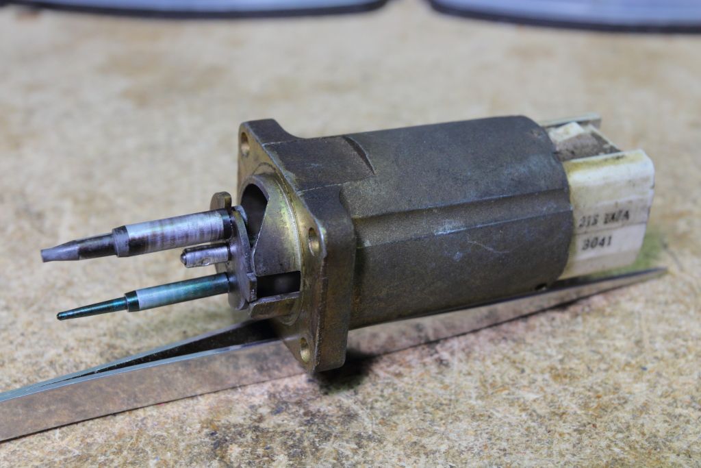 When the key is in and turned on the ECU will initialize the stepper motor by advancing the pins out to a full-closed position and then pulling them back. That is what happened on my unit so it's safe to say the ECU, the stepper motor wiring and the stepper motor are functioning. The motor is made up of two windings with taps at each end and in the middle. Refer to the wiring diagram on the last page. End-to-end resistance should be around 140-150 ohms with each half of a winding being half of the total value and no continuity to the exterior casting. The readings should be identical when comparing one winding to the other. It all tests good. 
|
|
#7
10-17-2018, 10:06 PM
|
||||
|
||||
|
I suppose the book must have a procedure for adjusting the carb... there must be a 'neutral' or 'test' mode, some method of setting the stepper motor to whatever position it's supposed to be in for making adjustments. Hell, it might be as simple as unplugging it while the ignition is off.
|
|
#8
10-18-2018, 08:47 PM
|
||||
|
||||
|
When on in open-loop there are several fixed positions the pins can be in depending on several on/off sensors. The manual states how to enable each mode for testing and that various carb adjustments can only be performed under certain ones. If you cannot reach the specified mode there's 20 pages of logic flowcharting to test each component in the CEC individually. I guess this is why people hate the BBD electronic carbs so much. If the emissions system is not working the adjustment instructions are useless and you are forced to fudge some things to get it close enough, or just do the nutter bypass and get another carb because computers are hard.
  I think my major strength here is that I'm approaching this from the opposite direction. Whereas most skilled mechanics of this era vehicle (and most jeep people) really don't know much about electronic emission systems my background is early computer theory and digital electronics so this is all making total sense to me as opposed to how the carburetor in general works. Again, I want to point out that the AMC repair manual is amazing. It's twice the thickness of your average Haynes manual and is pretty much identical to that of the average phonebook. It's like reading a tome. 
Last edited by MIPS; 10-18-2018 at 11:07 PM.
|
|
#9
10-19-2018, 04:44 PM
|
||||
|
||||
|
Quote:
Around '96 there was a new tenant in my old building who knew how to work on EFI, which I think ticked off the super who could fix just about anything else on a vehicle. However, the super serviced arcade machines regularly and often worked on TVs and other electronics, so go figure. Last edited by Jon A.; 10-19-2018 at 04:47 PM.
|
|
#10
10-20-2018, 12:07 PM
|
||||
|
||||
|
Finished cleaning and verifying some cabling and slapped the stepper back in for a test. Success.
 https://www.youtube.com/watch?v=b_BOvlLOrP0 The car sounds WAY better now at idle and you can smell it's not running as rich. Still not perfect but I think that might just be the O2 sensor needs to be replaced.
|
| Audiokarma |
|
#11
10-19-2018, 02:28 AM
|
||||
|
||||
|
And this is why I despised working on computer controlled cars with carburetors.
|
|
#14
10-20-2018, 10:57 PM
|
||||
|
||||
|
Sweet!
O2 sensor, but also perhaps those vacuum switches. You might want to get a vacuum gauge and test those switches to see that they open/close at correct vacuum (or at all). Nice that it says right on the wiring diagram how much vacuum they switch at. Vacuum gauge is a good thing to have for a carburated car, anyway. Last edited by MadMan; 10-20-2018 at 11:24 PM.
|
|
#15
10-21-2018, 09:25 PM
|
||||
|
||||
|
Great to see somebody fix one right instead of trashing ever little bit of emissions control. This is what made most 70's-80's vehicles so intimidating to me, that sea of vacuum lines and "doo-dads".
__________________
Bryan
|
| Audiokarma |
 |
|
|


 Hybrid Mode
