
|
|
|
#1
 07-31-2012, 08:41 AM
|
||||
|
||||
|
Need Help with Admiral 17T1
I've taken this project as far as I can, but I've only restored the audio. That's as far as I got with my last TV, a Motorola 12T2. At this point I'm hoping someone has the time to give me some direction. Otherwise I'll look for a job in a repair shop that specializes in TV for the blind.
The set worked well when I took it home two years ago. Several months later I took the chassis out for photos only, and subsequently it had nothing on the screen and barely perceptible audio. The set has been previously repaired with replacement of most of the paper and electrolytic caps. I have no business criticizing someone else's work, so I'll describe the repairs as being "expedient." But it worked. In the past few weeks I've ensured that the tubes are good; cleaned the chassis; replaced the remaining paper caps and one cardboard-tube electrolytic; repaired open connections on a couple of caps, and run the voltage tests a few times. I don't have the resistance data for this set, but I tried to check it against some of Sams data for the similar Admiral 19A1 (There are electronic differences and the tube numbering is different). I can get a good arc (between 1/4-inch and 1/2 inch) from the HV rectifier cap and from the high-voltage pin connections for the picture tube. I'll try to show the schematic and data in the post, but if I screw it up again, here's link to an album that has all that information and a few photos: https://picasaweb.google.com/coldrb/...eat=directlink     Finally, here's a link to the Wallace service data: http://www.earlytelevision.org/image...1_telaides.pdf Thanks, Winky 
|
|
#2
07-31-2012, 08:44 AM
|
||||
|
||||
|
Apologies...I have no idea why my photos aren't showing in the post.
- Winky
|
|
#3
07-31-2012, 02:55 PM
|
||||
|
||||
|
If you've got HV on the CRT and the filament is glowing, the problem is likely the cathode or grid voltages. Do the brightness or contrast controls have any effect ?
|
|
#4
07-31-2012, 04:28 PM
|
||||
|
||||
|
"...and the filament is glowing,..." Good point. The CRT neck is covered by metal shields and I've never seen the filament. I just took them off and put the CRT back in place. BUT I had the six potentiometers loose and the back of the chassis and didn't fasten them with their nuts. I turned it on and got the Big Spark indicator to slow down. I'll get back as soon as I can, but out-of-town visitors may delay me further. Thanks for the reply
|
|
#5
07-31-2012, 05:34 PM
|
||||
|
||||
|
Success!
So, the CRT filament glows nicely. A tweak to the brightness gave me this:
 https://picasaweb.google.com/lh/phot...eat=directlink I have to go to the airport now. When I get some more time I'll try to make it into an image. Thanks much. - Winky
|
| Audiokarma |
|
#6
08-23-2012, 01:52 AM
|
||||
|
||||
|
Lost Raster. If found, please call...
A few weeks ago I'd managed to get a raster on the Admiral 17T1. My grandsons were impressed and thought it would be cool if we could watch a movie on the TV.
 I got ready to make some more progress on this project, but now the raster is gone. I have nothing on the screen. I spent the last two days checking the voltages to compare with the data from a month ago. There are a few changes, but this in particular one caught my attention:  What happened to my 300 volts at pin 2? I've spent most of today blindly looking for a problem; checking resistors, retesting tubes, looking for open circuits, playing with controls. Audio is still OK and I get a good spark from the 1B3 cap. I've done everything I know how to do, and now I'm seeking mentors. These are links to the schematic and 3 pages of my most current voltage data. https://picasaweb.google.com/lh/phot...eat=directlink https://picasaweb.google.com/lh/phot...eat=directlink https://picasaweb.google.com/lh/phot...eat=directlink https://picasaweb.google.com/lh/phot...eat=directlink I'm grateful for any help I can get here. To show my appreciation I'll soon share my technique for repairing broken vacuum tubes. - Winky
|
|
#7
08-28-2012, 01:22 PM
|
||||
|
||||
|
Still No Raster
Sorry if it's rude to bring my own post back to the top. Five days of staring at the Admiral hasn't improved anything. I've rechecked everything I can think of.
If someone has the time to look at my issue and give me some direction, I'll be very grateful. - Winky
|
|
#8
08-29-2012, 01:40 PM
|
||||
|
||||
|
I peeked at the schematic (from http://www.earlytelevision.org/image...1_telaides.pdf ) and your set looks very similar to the Admiral 19A11 that I'm finishing up.
Like your set, mine had previously been partially recapped. Based on the appearance of those replacement caps, that work was done a long time ago, perhaps the 1960s or 1970s. The "newer" caps in my TV were plastic-coated cylinders, similar to the infamous bumblebees, but with different colors and markings. I assumed that they were the same junk -- paper caps in a plastic shell -- so I replaced all of them, too. Since you have lost voltage on the plates (pins 2 and 5) of the vertical output tube (V15), I'd start by checking the components connected to that tube, particularly capacitors, and especially any newer caps installed by someone in the past. A sudden change (loss of raster) suggests that some component failed. This is not unusual in restorations. Some component was marginal in the first place, and it croaks after an hour or two when exposed to voltage again. Capacitors (including micas in deflection circuits) are likely suspects, but resistors can fail, too. Other possibilities include a funky tube socket, an intermittent ("cold") solder joint, crumb of dropped solder, bent component lead that makes a short circuit, dirty potentiometer, or a wiring mistake. When a set has been worked on before, you can't assume that all of the work was correct. It would be easier to diagnose your problem with an oscilloscope, but it should be possible using your brain and a multimeter, although it may take longer. Phil Nelson Last edited by Phil Nelson; 08-30-2012 at 03:34 AM.
|
|
#9
08-29-2012, 02:26 PM
|
|||
|
|||
|
The 300 volts on pin 2 (6SL7) is derived from a bleeder chain starting at the DC high voltage. Look for a bad 1B3 or shorted 6KV cap on the DC side. That would explain the missing 300 v and no raster. Easiest way to test is to clip the low voltage end and check for high DC voltage on the open end. The raster will reappear when you find the bad one. Start with C-59
If no progress, check the bleeder chain starting at the low end and work backwards to the 1B3 filament. You need meter that safely measures up to 6KV as you work up to the 1B3. Without that, if you don't get any voltages at the low end, you can assume the chain is OK and there is no high voltage. The resistors may be off value, but none so far as to kill the high voltage without some arcing or smoke. Don
|
|
#10
08-29-2012, 10:02 PM
|
||||
|
||||
|
Thank you, gentlemen. Since I've already redone some of the previous repairs due to shorts and failed solder joints, I'll approach that first--redo all the modern caps and the electrolytics. Also the few resistors I've checked have drifted 10-25%, so I'll replace any that are off by 20% or more. That'll take me 1-2 weeks. I have a couple of spare 1B3's that test "good," so I can use those to rule out that cause. From the on-again/off-again picture and raster, an intermittent problem, like a bad tube socket or cold solder joint, is a likely suspect. I'll also look around for a kv meter.
And Don--Phil knows me better--you should understand that much of this is way over my head, This is first time I've confidently used the word "raster." For example, I have no idea what a bleeder circuit is, but instead of asking you, I'll take the time to figure it out on my own. That's the only way I can learn this stuff. I'm unteachable...but I can learn. Thanks again, Winky
|
| Audiokarma |
|
#11
08-30-2012, 02:25 AM
|
||||
|
||||
|
I wouldn't shotgun all of the replacement caps unless they look old. You got a raster before, so your TV may be pretty close to working.
"Old" is a relative term, I know. If the non-electrolytic replacement caps look like these old plastic-coated paper caps (perhaps with different colors), then I would get rid of 'em: 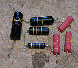 But if they are like these contemporary orange drops and little yellow guys, I would leave 'em alone for now: 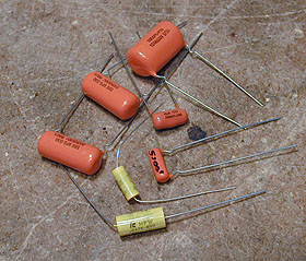 Other modern caps may be white tubes rather than yellow, or look like tan Chiclets. I would not re-replace the electrolytics just for the heck of it. If your set is still producing some HV, and many other voltages are in the right ballpark, the electrolytics can't be that bad. Bleeder chain: There is a bunch of high-value (1 megohm and higher) resistors between the picture tube and the vertical & horizontal circuits. Look at the lower right in your schematic. If you don't have a HV voltage tester, you can still test these with an ohmmeter. These values are not super critical, but who knows, one of them may have burned up and gone open. When I checked these in my Admiral 19A11, most were reasonable, but one of the 4.7 meg resistors had drifted to 9 meg, so out it went. Phil Nelson
|
|
#12
08-30-2012, 09:19 PM
|
|||
|
|||
|
Agree with Phil those high value resistors in the high volt do tend to drift and can cause among other things focus problems. I think I replaced all of them in my 17T1
GL Terry http://www.flickr.com/photos/4277432...in/photostream http://www.flickr.com/photos/4277432...n/photostream/ Last edited by 7"estatdef; 08-30-2012 at 09:23 PM.
|
|
#13
09-07-2012, 08:41 PM
|
||||
|
||||
|
Quote:

__________________
 Looking for zenith cobramatic parts -johnny the raster master!
|
|
#14
09-07-2012, 08:48 PM
|
||||
|
||||
|
Point out the damper tube on the schematic
__________________
tvontheporch.com
|
|
#15
09-09-2012, 03:30 AM
|
||||
|
||||
|
Identifying Potentiometer Terminals on Schematic?
I'm not sure that I have a damper tube, but the previous work has left so many "iffy" situations that I'm looking closely at every contact and joint as well as replacing resistors which are more than 10% above/below their specs and questionable caps. Some of the Megohm resistors are off by 30% or more. In a couple of places a new cap has been placed parallel to the original cap.
So while I'm waiting for new HV caps to arrive, I going through this chassis like Sherman's march through Georgia. Today's question is about correlating potentiometer terminals with the schematic. The pots for vertical cent. and horizontal cent. have four terminals. They also share two terminals. The previous repair guy has rewired so that the 4th terminal on each pot is unused. Here's my diagram of the pots and the schematic. Question is, have I identified the terminals correctly on the schematic? I'm getting ready put the wiring back like it is in the schematic.  Full Schematic https://picasaweb.google.com/lh/phot...eat=directlink Also, thanks to those who mentioned the bleeder chain. Some of those were 30% off and there was a newer resistor added in parallel to one of the originals. It's a good thing that I had been made aware of an entity called a "bleeder chain," because my first thought was, "Gee, I can save a lot of work by replacing these five resistors with one big one!" Then I thought, "But maybe there was a reason they used five resistors in series instead of one big one." Then I learned a little about power dissipation and a catastrophe was averted. - Winky
|
| Audiokarma |
 |
|
|


 Linear Mode

