
|
|
|
#1
 08-14-2013, 09:22 PM
|
||||
|
||||
|
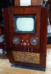
Motorola 7VT3 restoration
While waiting for some mica caps for my 630TS to arrive, I spent a couple days on this recent craigslist find. When I saw the photo in the listing, I assumed it was the black 7VT2 bakelite 7" set. So I was a bit surprised to discover it was actually brown when I went to check it out. I believe that makes it a model 7VT3. The back is missing so I'm not 100% sure.
3/4 of the hard to find gold knobs and an undamaged cabinet where enough to sell me on it. I borrowed the fine tuning knob from another set for the photo. 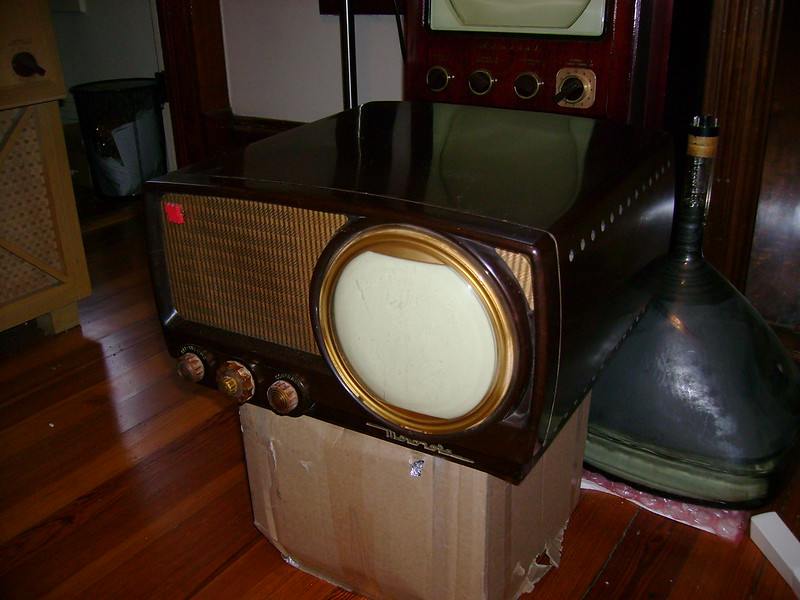 The chassis is stamped TS-18 with a date of Nov 16, 1949. Someone write tube designators all over it but two appear to be incorrect. They specify 6CB6 while the label inside the cabinet shows 6AU6  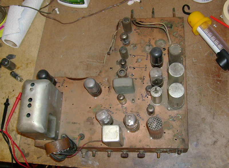 A few caps have been replaced. 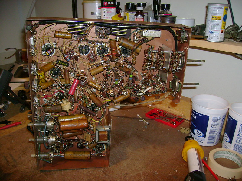 Also, some resistors associated with the vertical height and centering. That 68K in the foreground should be a 2.2M and the other 68K should be 4.7M. More on that later...  All the tubes were present including the ballast so I gave it a controller power up. A bit of fiddling got me sound decent sound and a faint raster. 

|
|
#2
08-14-2013, 10:41 PM
|
||||
|
||||
|
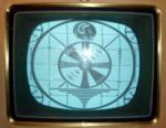
I replaced all the paper caps in stages, pausing for a power up periodically.
Here's the first semblance of an image after replacing those incorrect vertical resistors and a few vertical caps. While doing so, I discovered a 22 Meg feedback resistor had drifted up to over 35M which cause the oscillator to run much slower than it should. I think those 68K resistors mentioned above were an attempt to fix this issue. 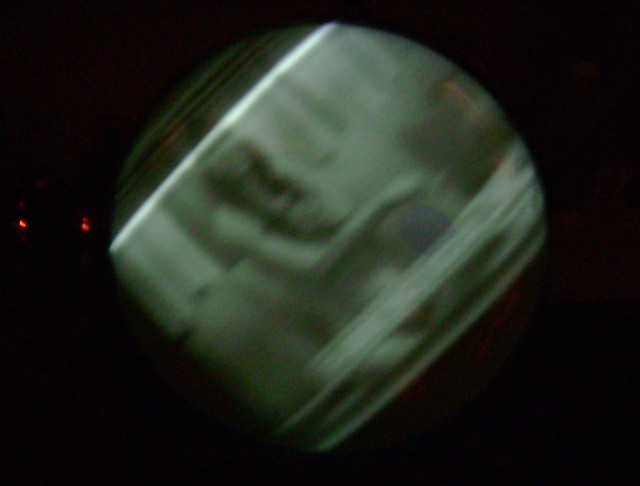 A few more replaced caps in the sync and horizontal circuits resulted in a stable image 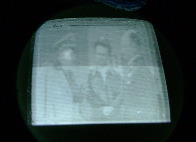 Replacing all the HV caps resulted in a brighter raster. 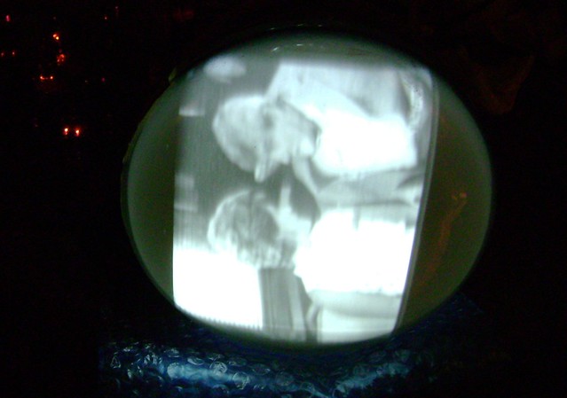 Finally, after replacing all the paper caps. 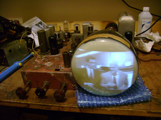 Next up, I'll do the electrolytics and selenium rectifiers.
|
|
#3
08-14-2013, 11:00 PM
|
||||
|
||||
|
I discovered something rather odd while working on this chassis. Although it's stamped TS-18, it differs in a few ways.
Here it is next to a "normal" TS-18 (on the right) that is dated just four weeks earlier. Notice the 7VT3 chassis has more holes stamped in it and there are parts sticking out along the IF strip. 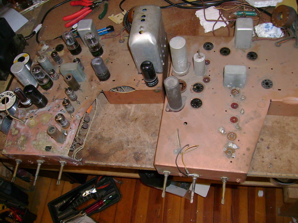 Here's a closer look at the IF area. This trimmer cap is not shown in any service info I can find for either the TS-18 or T-18A. No trimmer cap on the TS-18A either. That could make an alignment a bit tricky. I'll trace out the circuit and post my findings later. 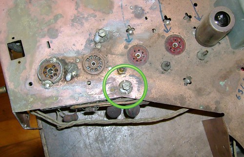 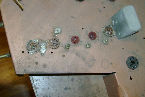 Finally, here it is next to a TS-18A chassis dated about 8 weeks later. Notice it's not copper plated and the chassis punchouts are identical, but the horizontal tranny is mounted on the outside like it is on all TS-18As. My conclusion is that I have some sort of proto TS-18A version. I seem to have a knack for finding odd Motorola 7" variations ! 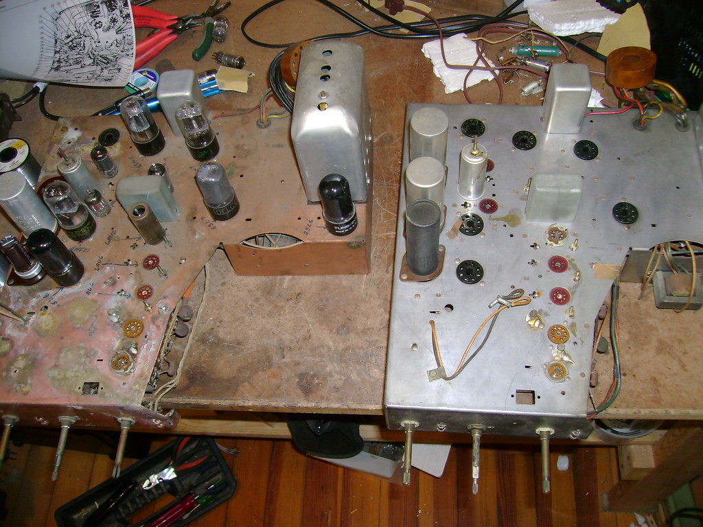
|
|
#4
08-15-2013, 02:06 PM
|
||||
|
||||
|
Here's a closer look under the hood.
I believe traps have been added to the IF coils and some sort of filter to the mixer grid bias. The big white 3.3uH inductor is open so the mixer grid is floating right now. That can't be good  . .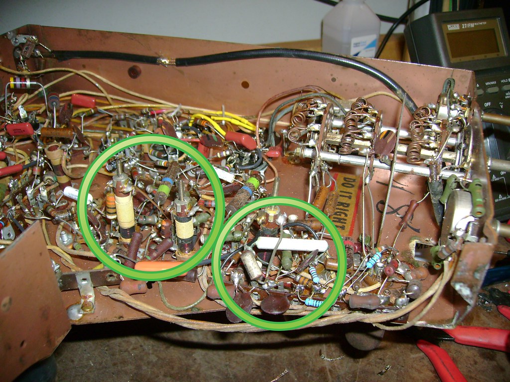 Here's a stock TS-18 for comparison. Notice there are no tuning slugs on the IF coils and no inductor to the mixer grid. Also a few caps are mica vs ceramic. 
|
|
#6
08-15-2013, 04:36 PM
|
||||
|
||||
|
Just be sure you "DO IT RIGHT"
 They seem to have dropped that in later sets.
|
|
#7
08-16-2013, 10:44 PM
|
||||
|
||||
|
After replacing the electrolytics and seleniums, here's the image I get. There's clearly some interference/snow leaking in from somewhere.
For now, I've bypassed that "extra" trimmer capacitor and will attempt an alignment following the stock instructions. I'll leave the added traps alone. 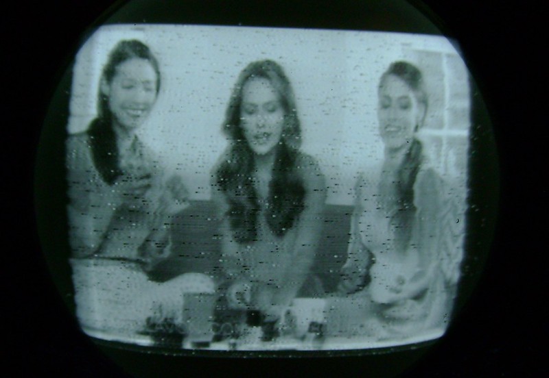 Once I get this set running better, I hope to do a little experimenting with a 3JP1 (green phosphor) and 3JP12 (orange phosphor) CRT. They have identical bases and pinouts, but there's a 3rd button anode and the anode voltages are about half the 7JP4. I figure a little creative tinkering with the voltage divider taps will work. 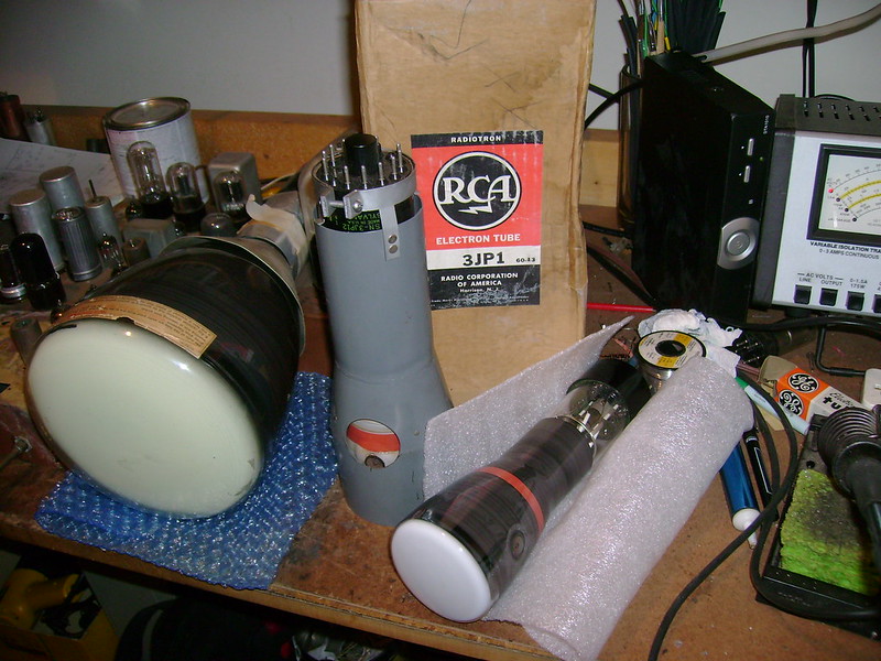
|
|
#8
08-18-2013, 03:53 PM
|
||||
|
||||
|
I've been working on the alignment today and confirmed those are traps. One for the low side and one for the high side of the response.
You can see the dip caused by the high side trap on the right of the response curve. I've got it just about tweaked correctly to give a 3.5 MHz bandwidth.  Here's what I started with. 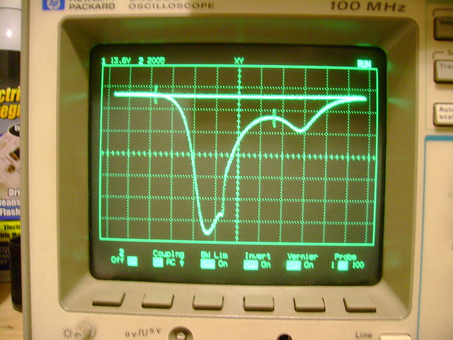 I also got a suggestion the picture interference could be caused by HV arcing. I couldn't find any evidence of that under the chassis so I popped the HV cover off for a look inside. I found the original Motorola branded 1B3/8016 installed. Cleaning out a dead spider and replacing the 1B3 made no difference. 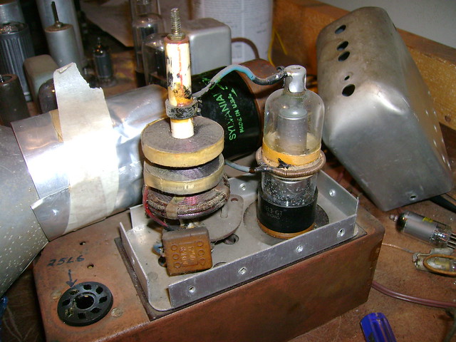
|
|
#9
08-23-2013, 08:20 PM
|
||||
|
||||
|
This set is really starting to get to me. I've even gone so far as to replace the HV coil assembly, but the interference remains
 I figure I'll drag out my B&K 1077 next and start working my way back from the video amp. That's assuming I can get a clean image at the video amp. 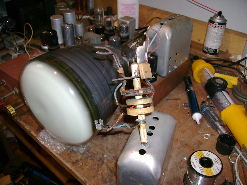
|
|
#10
08-23-2013, 08:37 PM
|
||||
|
||||
|
Bob, have you tried a different 7JP4? Wonder if it could have a little internal leakage getting into the video.
|
| Audiokarma |
|
#11
08-23-2013, 09:36 PM
|
||||
|
||||
|
Yes, just this evening I did. I've also swapped out every tube including the ballast. Nothing I've tried has made the slightest bit of difference. So annoying because otherwise the set is playing great!
|
|
#12
08-24-2013, 07:43 AM
|
||||
|
||||
|
What happens when you flip the CRT to the backside, away from the chassis?
|
|
#13
08-24-2013, 07:45 PM
|
||||
|
||||
|
HV noise on video B+?
It kinda looks like there is a periodic pattern to the video noise. Could it be noise on the video B+ from the HV oscillator? Maybe if you could drive the set with RF with no video modulation you could see the noise on the video stages on an oscilloscope and see if it is the same frequency as the HV supply oscillator. You could also try grounding the grid of the first video amp to see if it is in the video stages or before the first video amp.
|
|
#14
08-25-2013, 04:33 PM
|
||||
|
||||
|
Quote:
Quote:
|
|
#15
01-31-2014, 02:37 PM
|
|||
|
|||
|
Hi Bob,
I had an idea about RF interference on the Motorola 7VT3. Sorry you didn't have the right test gear at the ready. I know I hate switching between projects for logistical reasons - but that is the way of the world, yes? On the RF interference, short of getting your signal injection / trace gear out, here are some ideas. o On the IF alignment, could it be that the extra hump in the passband is where the interference is creeping in. Maybe the speckled interference is just snow from noise in the hump portion of the IF passband. We see the picture from the normal passband information, and we add noise to it with the hump band information (noise). o Are the low-end and high-end traps swapped? At time 7:50 in ''Motorola 7VT3 restoration pt3o?,'' try to keep turning the low trap through the passband and use it to knock out the hump on the high side. It seemed like the tuning slug was all the way out. Maybe it has to go back in a lot of turns. o I don't remember what it was for, but you took out an inductor - the one you forgot to order from Mouser. Could this be a trap for the extra hump? Anyway, good luck. I really like your videos. Best of all, I like that don't have to do the work.  Cheers, Steve
|
| Audiokarma |
 |
|
|


 Linear Mode

