
|
|
|
#31
 12-23-2013, 03:20 PM
|
||||
|
||||
|
Nice! Something to keep in mind when using OTA channel 6 as a test signal is that the sound carrier is much stronger than the video. I usually get booming sound with just a scrap of wire for an antenna but need a good antenna to get a decent image. I'm a couple miles west of downtown BTW.

|
|
#33
12-24-2013, 03:21 PM
|
||||
|
||||
|
It's hard to say. Could be the way the RF signal is being injected, weak tubes, bad alignment, bad caps/resistors, etc.
Check the easy thing first - the antenna connection. There are three screw terminals on the back. If you have a 75 ohm source, use the top two screws, If it's 300 ohms, use the outer two screws. As for tubes, there should be several 6AU6 or 6AG5 in the IF sections. You can try swapping those around if you don't have any spares. Also, since you're local, you could swing by my place and I can check it out for you.
|
|
#34
12-26-2013, 05:12 PM
|
||||
|
||||
|
Guess what, I found a small "hidden" paper cap I missed, 0.004mfd @600V. I replaced it an the picture cleared up, and my height is restored.
The H and V holds are now unstable though, very touchy. Also, seeing some retrace lines. I am going to check some resistors near the brightness control for the retrace lines. I am also going to look at replacing some tubes that hopefully will help the hold issue.
|
|
#36
12-26-2013, 08:25 PM
|
||||
|
||||
|
Quote:
If you have a scope, check to see if the sync separator is working properly. If not check for voltages off spec in that circuit. Try substituting the sync tube. Oh the retrace issue, remember this set is electrostatically swept and therefore you don't have the usual big voltage signals being generated that normal B&W TVs use to key the blanking. In fact, the high voltage oscillator is not even running on the horizontal sweep frequency in this set! To the best of my knowledge there is no blanking in this set, other than the video itself. All the Motorola 7's and most other 7 inch electrostatic sets have iffy blanking. If memory serves me correctly the 8BP4 you have uses the same electron gun as the 7JP4 with simply a larger bulb on the other end and the 8's seem to be a bit more critical on retrace than the 7's. I assume that you have replaced all the 6KV capacitors in the set and the paper capacitors in the video output stage, especially the one going to the cathode of the CRT. Make sure the 100K resistor going from the filament of the 1B3 to the anode (pin 6) of the CRT has not increased in value. Check the value of the 150K resistor between the control grid of the HV Osc. and the ground. (That is High Voltage osc. and not the Horizontal Sweep osc.) Your next step is to adjust the high voltage. To do this on this set, turn the set off channel and and lower the brightness slightly. Using a plastic stick gently slide the gimmick (the spring around the belly of the 1B3/8016) up and down while adjusting the screen for the maximum brightness. After this, readjust the focus. Now feed a signal into the TV and adjust the brightness and contrast the best you can to get rid of the retrace. James
|
|
#37
12-27-2013, 01:23 AM
|
||||
|
||||
|
Quote:
__________________
"Face piles of trials with smiles, for it riles them to believe that you perceive the web they weave, and keep on thinking free"
|
|
#38
12-27-2013, 11:50 AM
|
||||
|
||||
|
Thanks for all of the tips guys, being my first vintage TV resto I am pleased with it so far.
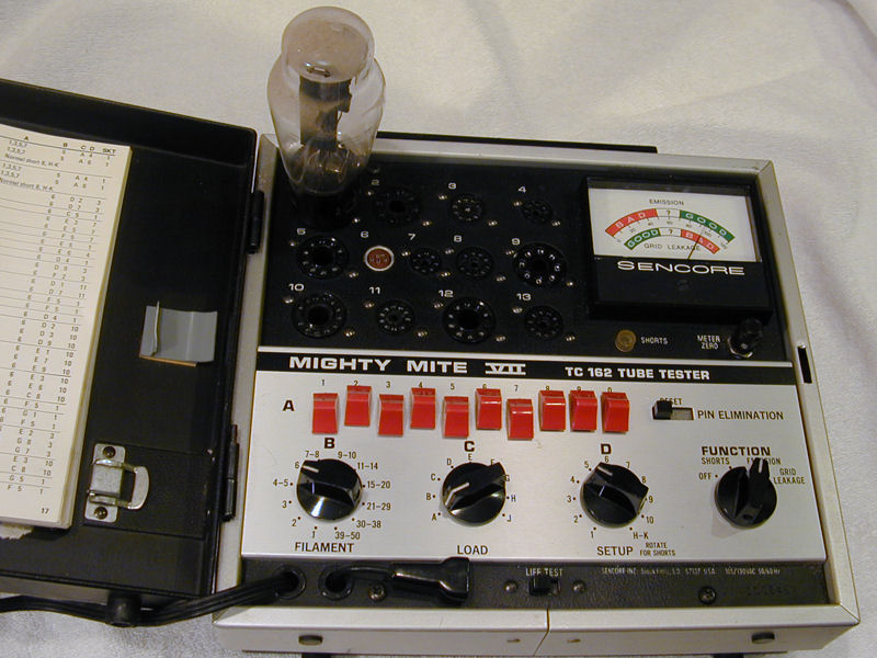
Thanks for the tip on the HV, never knew how to set properly. Once I get all of my tubes squared away I'll also set the voltage. I am pretty sure one of three 12SN7GT's I have in my chassis is flakey, as depending on how I suffle them around in the chassis I can lose all picture reception. I have been watching a few tube testers on ebay in the $50 range, I will likely bid on one this week or so. Also, are replacements of the power switch/volume available? I typically have to jiggle the volume knob in order to get a full sounding audio, or else it is just treble. 
|
|
#39
12-27-2013, 12:36 PM
|
||||
|
||||
|
Quote:
 Some tube functions (notably, oscillation) can't be tested on any tester. In those cases the best test is substitution with a known good tube. In a few such cases, I've had to try as many as half a dozen "tests good" tubes before I found one that oscillated properly in a particular TV. Regarding the volume, have you already tried cleaning the volume control? See: http://www.antiqueradio.org/FirstStepsInRestoration.htm . Regards, Phil Nelson Phil's Old Radios http://antiqueradio.org/index.html
|
|
#41
12-27-2013, 02:08 PM
|
||||
|
||||
|
A potentiometer with a ganged power switch is a pretty common item. AES carries a few:
http://www.tubesandmore.com/products...Potentiometers You could also look at suppiers such as http://www.mouser.com/, http://www.alliedelec.com/ , or http://www.digikey.com/ . Mark Oppat also stocks controls, and he can even rebuild old ones: http://www.oldradioparts.net/controls.html Phil Nelson
|
|
#42
01-04-2014, 07:41 PM
|
||||
|
||||
|
Thanks for the tip, I will probably send in the control to get rebuilt or trade it in for one.
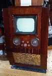
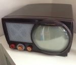
I have some updates, firstly I replaced most of the tubes with NOS(they were cheap) and the picture is better. Still seems like the brightness is too high even though I have it turned all the way down. It's like the text "blooms". I did adjust the HV, but it did not really help much. I posted on updated screenshot. Also, I bought some new speaker fabric on AES. I didn't want to ruin the original in case I wanted to switch back, so I made a cardboard copy and upholstered the fabric to it. See pics. I used 2 layers of fabric, one layer was too transparent. I think the new fabric adds a little character to the set, I'd like to add one of those red Motorola wave logos to the set also, I think it would look sharp. We'll see.
|
|
#43
01-04-2014, 08:21 PM
|
|||
|
|||
|
Replacement grill cloth is readily available at several different company's. Just google speaker grill cloth or fabric. One of them is at www.markertek.com that looks just like the picture you have of your faded one. Also if your putting your light bulb in series with the AC line, the bulb will light bright as the tubes will be pulling current to light the filaments. It's best to put the bulb in series with the B+ line, right before the rectifiers (diodes) which replaced the selenium's. As a compliment looks like you did a really good job replacing the old wax capacitors and resistors. If you have or can get a hold of a variac in which you can bring the line voltage up slowly, you can check things out at a much lowered voltage, especially the voltages at the filter capacitors, (electrolytic's), and of course watching for parts overheating or smoking. Take your time and I'm sure you will have a nice working relic.
|
|
#44
01-05-2014, 12:31 AM
|
||||
|
||||
|
I finally got everything back in the cabinet tonight, but after I turned on the TV I noticed a problem I didn't have earlier. The picture is wavy, or more like a wave travels from the bottom of the screen to the top, slowly. I didn't change anything electrically. I tried pulling the chassis again and running it outside the cab with the pic tube still installed same problem. Also reseated all the tubes.
Video below, what happened, what could cause this?  https://www.youtube.com/watch?v=Va4I...ature=youtu.be
|
|
#45
01-05-2014, 01:47 AM
|
||||
|
||||
|
You mentioned new tubes, it is likely 60Hz AC from the heater of a tube leaking to a cathode and into the deflection system. The vertical deflection frequency of the post 54' color system we feed our sets is 59.94Hz and thus when 60Hz power line frequency gets into the circuits associated with the picture it results in a horizontal bar of image disturbance that rolls vertically with respect to the image. The nature of the disturbance depends on what tube is leaking and the circuitry of the set. I'd guess it is the horizontal deflection or possibly synch tube that is the problem, but if you did not change those or putting the originals back does not fix the problem then try putting all of the originals back in one by one and power it up between each to see if the problem goes away...As soon as it goes away you will know that the last tube you changed before that power up is defective.
__________________
Tom C. Zenith: The quality stays in EVEN after the name falls off! What I want. --> http://www.videokarma.org/showpost.p...62&postcount=4
|
| Audiokarma |
 |
| Thread Tools | |
| Display Modes | |
|
|


 Linear Mode

