
|
|
|
#46
 09-11-2014, 11:59 AM
|
||||
|
||||
|
I could use his help right about now
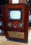
 Replacing the drive control has stopped the fuse from popping. It appears to be tin plated but I couldn't really see any whiskers. 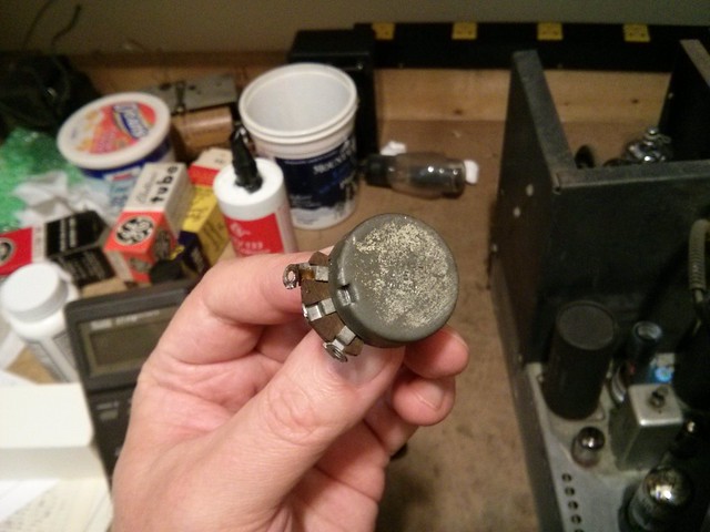 All the resistors and capacitors on the HOT have been replaced and DC voltages seem reasonable. The cathode waveform matches whats shown in the service info. 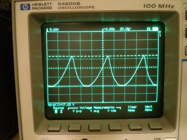 I've also tried swapping out each of the the three tubes inside the HV cage, but the low HV issue remains. Only about 6.5 kV under load. Just for the heck of it I installed a full size CRT, and you can see how dim and unfocused it is.  So it seems to me that leaves the two high voltage ceramic caps inside the cage, the yoke and the flyback as culprits 
Last edited by bandersen; 09-11-2014 at 12:06 PM. 
|
|
#47
09-11-2014, 03:48 PM
|
|||
|
|||
|
Capehart 325
While looking on ebay, I noticed a similar one located one state up from me. Viewing the listing showed it had been robbed of some parts: tubes and looks like 12" speaker. What actually concerned me was the power transformer laying in the bottom of the cabinet with frayed wires while a power transformer was still mounted in the chassis. All that, the $100 opening bid, and the condition of the cabinet was enough to turn me off of it.
http://www.ebay.com/itm/Original-195...item3395211702
|
|
#48
09-11-2014, 06:10 PM
|
||||
|
||||
|
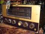
At least I got a photo of the missing HV cover now

|
|
#49
09-11-2014, 06:55 PM
|
||||
|
||||
|
Quote:
Quote:
|
|
#50
09-11-2014, 07:55 PM
|
||||
|
||||
|
Quote:
Quote:
|
| Audiokarma |
|
#51
09-11-2014, 11:37 PM
|
||||
|
||||
|
Quote:
if the cathode of the 6W4 is reading 355, it is too low & is a possible indication that something in that immediate circuit is drawing too much current. after all, that is the B-Boost circuit. that also could be the cause of the low B+ voltage (250v) Last edited by robert1; 09-11-2014 at 11:52 PM.
|
|
#52
09-12-2014, 12:20 AM
|
||||
|
||||
|
Yes, I got 355V on the cathode. I was referring to Sams 112-3 which more closely matches my chassis and states 250 VDC for the 6W4 cathode. For example I have a 6AL5 video detector rather than a 1N34 diode as shown in Sams 160-2.
Last edited by bandersen; 09-12-2014 at 12:27 AM.
|
|
#54
09-12-2014, 11:49 AM
|
||||
|
||||
|
There's one 500pF 20kV doorknob cap under the 1B3 rectifier socket. Very difficult to get at. I'm going to try a different yoke first.
|
|
#55
09-13-2014, 02:04 PM
|
||||
|
||||
|
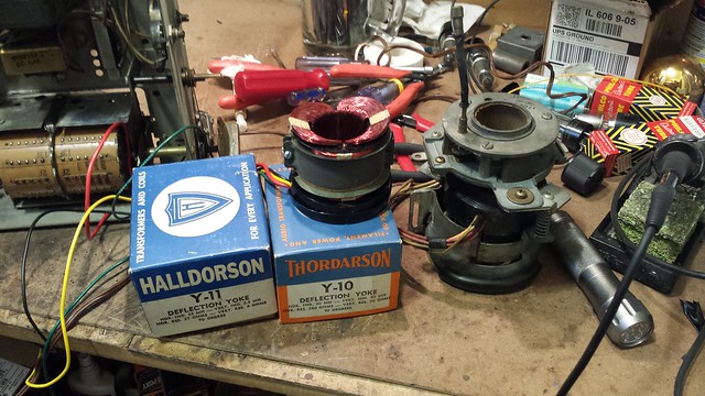
I dug up another RCA yoke plus a Y-10 and Y-11 to try. All are 70 degree yokes.
|
| Audiokarma |
|
#56
09-13-2014, 02:11 PM
|
||||
|
||||
|
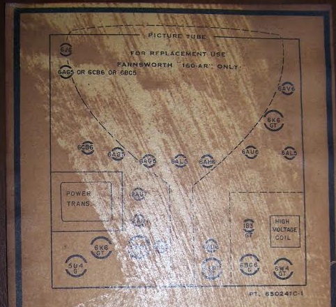
The owner also sent me a photo of the tube chart showing it used a Farnsworth 160-AR CRT.
|
|
#57
09-13-2014, 03:22 PM
|
||||
|
||||
|
Got a little more HV (~9kV) with the second RCA yoke also marked Y-17.
|
|
#58
09-13-2014, 08:50 PM
|
||||
|
||||
|
Could there be a shortage of HV filtering when using that test CRT?
|
|
#59
09-14-2014, 01:45 PM
|
||||
|
||||
|
Well there's a 500pF HV filter cap and when I tried a 16KP4 with aquadag coating, it didn't help. My Farnsworth 160-AR picture tube has no coating at all. Not sure if it originally did or not.
|
|
#60
10-12-2014, 02:16 AM
|
||||
|
||||
|
What's this?
An active restoration project thread that has gone nearly a month without a post? Heresy! I'm scratching my head along with you on the HV issue but I can at least provide one facepalm-worthy suggestion to another annoyance you're having... Put the test CRT in "upside down" so the anode connection is on the other side and the HV lead runs across the top. The test CRT is small enough to probably allow the HV lead to still reach, and then the weird spring on the HV lead won't put up so much of a fight. There appears to be enough slack on the socket wiring to rotate 180 degrees without issue. Continuing this thought-process, consider the possibility that the damned spring is sapping the HV through cracks in the very much vintage rubber HV lead insulation? That would explain the low HV measurement even with the tube disconnected. I'd bypass the whole HV lead assembly with a modern replacement and see if anything improves. There's no hidden resistor in series up under the suction-cup either, right? You've checked the filament current limiting resistors up under the HV rectifier, too? Swap the rectifier out for a string of microwave oven rectifier diodes? Aside from the flyback and doorknob cap, the HV lead is one of a rapidly dwindling list of things you haven't yet substituted for known or presumed working parts...  Going further down the grasping-at-straws path, pop an analog milliamp-meter in series with the HV supply directly after the rectifier and see if there's more current than expected being drawn. Obviously only a floating analog meter will work here. I'm sure someone makes a digital meter capable of measuring 0-100mA up around the 15kV zone, but it probably comes with a hefty price tag, and it sure isn't something you're going to use very often anyway.  Even further down the "Nothing makes any sense, why doesn't it just work!" path: Is your chicken blood fresh, or are you using that freeze-dried just add water stuff they sell to the wannabe-wiccans? Perhaps the bleached skulls need more dribbly candle wax on them, or maybe they need less. Swirl your tea-leaves in the opposite direction next time... Try everything! (In moderation.) 
|
| Audiokarma |
 |
|
|


 Linear Mode

