
|
|
|
#28
 08-08-2015, 01:04 PM
|
||||
|
||||
|
Back to the video preamp plan, with a question about the heater connection. I posted the original article at:
http://antiqueradio.org/art/RCA_Broa...eo_Preamps.pdf The plan I'd like to build is on the last page of the article, which says, "The heater connection is made to pin 4 of the adaptor socket." The heater connection is to service the 12AT7 tube on the preamp. Here's the 12AT7 basing diagram, showing that its heater is center-tapped at pin 9. 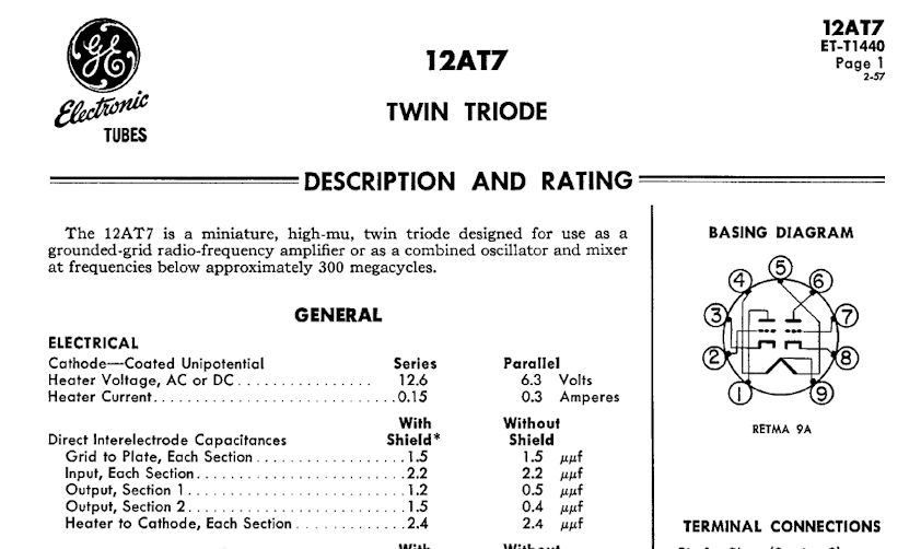 The article tells you to connect the heater connection to pin 4 of the adaptor socket. That's clear, but I want to make sure I understand the way they drew the heater connections in the preamp schematic: 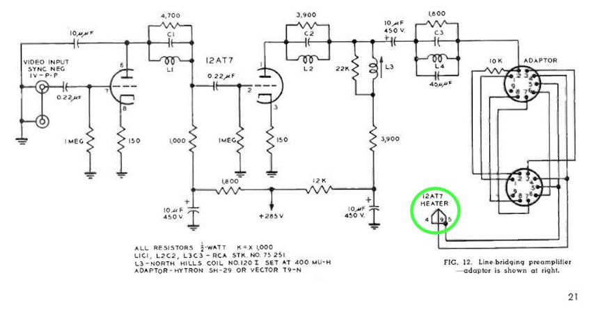 The drawing seems to show pin 4 of the adaptor connecting to pin 9 (the center tap) of the 12AT7. And pin 5 appears to be jumpered to pin 4. Or am I reading the schematic incorrectly? (The ground connection for the heater is made through pin 5 of the 6CL6 1st video amp tube, whose socket the adaptor plugs into.) Phil Nelson 
|
|
|


 Threaded Mode