
|
|
|
|
|
#1
 05-15-2015, 12:48 AM
|
||||
|
||||
|
Here's the whole schematic in four parts:
http://antiqueradio.org/art/RCACTC-4SchematicPart1.jpg http://antiqueradio.org/art/RCACTC-4SchematicPart2.jpg http://antiqueradio.org/art/RCACTC-4SchematicPart3.jpg http://antiqueradio.org/art/RCACTC-4SchematicPart4.jpg The bit you're looking for is in Part 3. In a nutshell, the outputs from T115 go to the grids of the R-Y and G-Y demodulators (V125). One of them also goes to the chroma phase detector (V120). Phil Nelson 
|
|
#2
05-17-2015, 07:11 PM
|
||||
|
||||
|
While messing around with the breadboard circuit, it occurred to me to use the scope to look at the phase relationship of the outputs from the quadrature transformer. I was able to adjust the transformer so that they were 90 degrees out of phase, but one output was still lumpy. Perhaps not surprising, considering that the breadboard circuit was crudely built, hanging off the chassis by various foot-long leads.
I disconnected the breadboard circuit, replaced a couple more resistors around the R-Y/G-Y demodulator, and reconnected everything with the old T115 transformer in place. I also dug up a second scope probe so that I could view both outputs at once. Whaddya know, both outputs are nice sine waves! Using the top and bottom adjusters on T115, I got them into a 90-degree phase relationship: 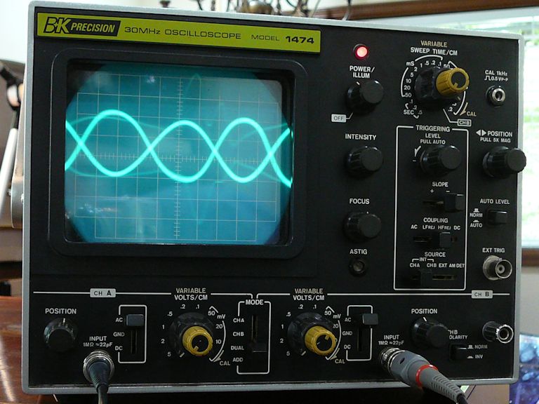 By switching the time base to channel B, I was able to get a purty-good 90-degree circle, as described in my scope manual: 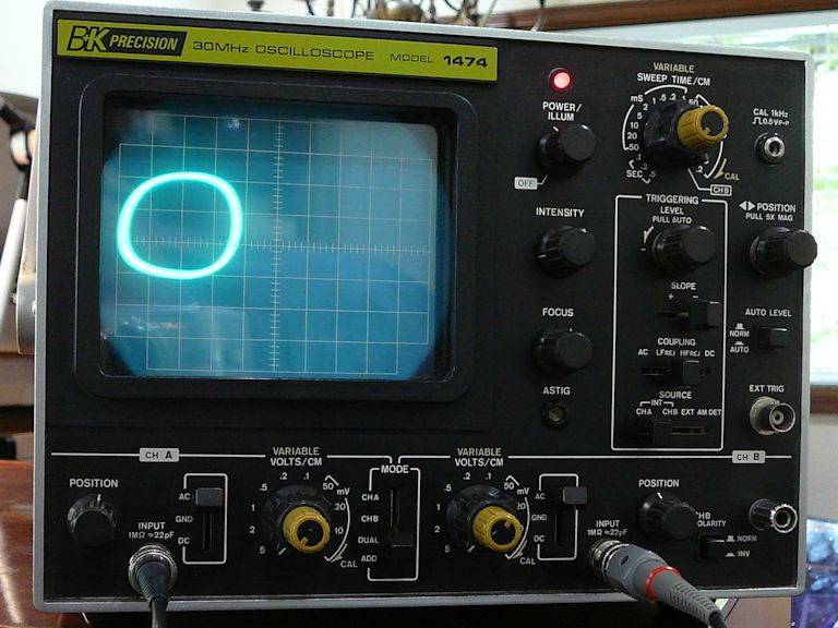  This was all done without reference to other circuits or to what appeared on the screen. When I looked at the screen, I saw these color bands, which can be made to stand still:  Not a correct picture, but my goal here was to confirm that: -- The chroma oscillator works. -- The quadrature transformer passes the 3.58-MHz signal. -- The transformer adjusters affect the phase relationship of its outputs. If these things are indeed working correctly, I'll cross 'em off the list and look elsewhere for solutions. Phil Nelson Last edited by Phil Nelson; 05-17-2015 at 08:43 PM.
|
|
#3
05-20-2015, 12:16 PM
|
|||
|
|||
|
Phil,
Since you've already done the alignment procedure per the manual, presumably the tint ('hue') control shows some evidence of working when you turn it. - The display looks like possibly one of the two demods is really wonky or maybe not working at all. Assuming the hue control is working, I would try this.. using a cap of .01 - .047 or thereabouts, short out each of the demods in turn, watching to see what the tint control does while one demod is shorted. - At the 12BH7 demod tube V125A, short the plate (pin 1) to ground*. This kills the R-Y signal. On a normally working set, the display will show some colors missing, but with the tint control still functional. Now short the plate of the other (G-Y) channel (pin 6). You should get a different set of colors, and the tint control should still work. - If either channel shows little or no color, and/or the tint control has little or no effect, I would look further into that channel for the problem. - Of course if both channels pass the test, then the wonky-color fault lies somewhere else. - *Or to B+, doesn't matter since it's signal ground. Last edited by old_coot88; 05-20-2015 at 12:20 PM.
|
|
#4
05-19-2015, 02:37 AM
|
||||
|
||||
|
Ramsey Electronics made several frequency counter kits in the late 1970s to early 1980s, and they also had a kit called a "frequency counter calibrator". It was a 3.58 MHz oscillator that you wired into your working color TV set, and it would phase-lock to the TV set's chroma oscillator. You then tuned the set to a network TV show (they were specific about that), and then adjusted the counter to display exactly 3.579545 MHz. It was interesting-all of the networks were within 1 Hz, and some of the local stations were off by several Hz or more.
__________________
Chris Quote from another forum: "(Antique TV collecting) always seemed to me to be a fringe hobby that only weirdos did."
|
|
#5
05-20-2015, 06:46 PM
|
||||
|
||||
|
Now that the oscillator is running at the correct frequency, do what I did:
grab a pair of plastic diddle sticks, put one in each core of the quad x-former. Put a mirror in front of the set, so you can see the screen while you twist the diddle sticks. Tweak both cores with a color bar pattern on the screen till you see the correct bars, and make sure the tint control is centered when you do it otherwise you'll end up with not a lot of range when you're done. If you're able to get good bars I'd call it a day, if it looses lock during the procedure zero beat the oscillator again and repeat- remember that the phase detector and local oscillator are linked together, so a change in one affects the other.
__________________
Evolution... 
|
| Audiokarma |
|
#6
05-20-2015, 09:42 PM
|
|||
|
|||
|
If still wonky after adjusting T115 cores for best display, see what effect adjusting T114 core has.
Also check voltage on V125 plates (pins 1 and 6). Should be about 36V. If not correct, check resistors - R256 (110K), R258 (180K) R262 (150K) R283 (47K), R282 (3.3K) R286 (3.3K) . Last edited by old_coot88; 05-21-2015 at 01:00 AM.
|
|
#7
05-21-2015, 01:21 AM
|
||||
|
||||
|
I spent some time adjusting T115 with two diddle sticks while watching the color bars, but didn't reach Nirvana. Lots of colors, but no clear path to the right ones. I think there is more going on here than mere misalignment. The lock doesn't seem very strong, either. The bars were prone to start pulsing, and tweaking the reactance coil did not always cure that in an obvious way.
I checked some voltages on V123, the 6AG7 demodulator driver: pin 4: 0 (0 expected) pin 5: 7.1 (6.2 expected) pin 6: 175 (230 expected) pin 8: 248 (280 expected) The "expected" voltages are from the RCA schematic; the Sams manual gives lower voltages for pins 5 (5.5v), 6 (200v) and 8 (250v). T114's secondary has continuity, measuring about 4 ohms from terminals A-B. I checked the plate voltages of V125, the 12BH7 R-Y/G-Y demodulator: pin 1: 33v pin 6: 16v I tried scoping the signal coming from T113, the bandpass transformer, and following it through the demodulator driver transformer (T114). Here is the waveform at the grid (pin 4) of the 6AG7 demodulator driver:  Here's the waveform at the plate (pin 8) of the demod driver:  Here's the waveform at terminal A of T114, the demodulator driver transformer:  And here's the waveform at terminal D of T114:  Out of curiosity, I put the frequency counter at these points. For what it's worth, it measured 3.80 MHz at the plate of the demod driver tube, 3.69 MHz at terminal A of T114, and 3.74 MHz at terminal D of T114. Next stop: checking resistors. Phil Nelson Last edited by Phil Nelson; 05-21-2015 at 03:05 PM.
|
|
#8
05-22-2015, 01:40 AM
|
||||
|
||||
|
Quote:
Maybe I will break down and install the replacement quadrature transformer. But first, I want to mess around with the breadboard circuit a little more, to see how close I can get to the ideal frequency. If there's any component tweaking to be done, I'd rather do it on the breadboard. Phil Nelson
|
|
#9
05-22-2015, 10:09 AM
|
|||
|
|||
|
Quote:
Quote:
|
|
#10
05-23-2015, 12:40 PM
|
||||
|
||||
|
I lifted those resistors to re-check, and didn't find anything more than 10% off spec, but I replaced them anyway. Now I have replaced most of the resistors on the video board hanging off the side of the chassis.
None of the voltages on the 12BH7 (including plate voltages) are very close to spec. These circuits have a bunch of 2-watt resistors connected to the +380V line. I don't keep many 2-watt resistors on hand, so I'm off to the local store to restock. Phil Nelson
|
| Audiokarma |
|
#12
05-28-2015, 03:53 PM
|
|||
|
|||
|
Will the genny he's using make solid-color blank displays?
|
|
#13
05-26-2015, 03:32 PM
|
|||
|
|||
|
Just a shot in the dark, but did you inspect lead dress carefully for any wires shorting? Looks like possibly a melt-thru of the insulating sleeve on that resistor going to lug #2 of the tube socket.
|
|
#14
05-26-2015, 04:50 PM
|
||||
|
||||
|
It's not beautiful, but I have checked it all carefully and there are no shorts or wiring errors.
Phil Nelson
|
|
#15
05-27-2015, 12:17 PM
|
||||
|
||||
|
I think your most telling post came around #134. In that post you put up
screen shots of the O'scope of the input of the video amplifier. This was also smartly compared to a different set, a ctc 11, not that it matters. What it does say, is that your scope, scope probe, are not distorting, or un-necessarily loading the circuits. The scope image also says to me that there is serious overshoots on vertical rise items in the circuit. This can cause ringing, which could also be causing harmonics, and other distortions around the burst signal as well..... You should fix this first, I think it's giving you trouble down the line... I think your problem is not in the color osc circuit, but before it..... You need to figure out why your video detector circuit is allowing much higher frequency response (is what I believe is going on) This could be an open coil, or open cap in and around the Video IF and video detector area... PS You already showed that your color osc works on yer breadboard thing. Feed that osc a buncha noise and I bet it quits, or looks like it quits. Your freq. counter acts like it does when noise is present too, locking on different frequencies..... It would be neat if'n you had a spectrum analyzer to see what's getting to the vid. amp and ocs. grid. just my 2 nuts worth.... (not those nuts) .
__________________
Yes you can call me "Squirrel boy" Last edited by Username1; 05-27-2015 at 12:33 PM.
|
| Audiokarma |
 |
|
|


 Hybrid Mode
