
|
|
|
#91
 07-07-2017, 12:33 PM
|
||||
|
||||
|
Looking good!
How is the horizontal linearity on yours? Mine is a bit stretched on the left side... but I remember from childhood that the test patterns always looked a bit lopsided. My father took it in for repair once, but it was never quite right. jr 
|
|
#92
07-09-2017, 09:45 PM
|
|||
|
|||
|
Actually the picture is pretty good. I haven't hooked up a test pattern yet. I'm watching Kolchak.
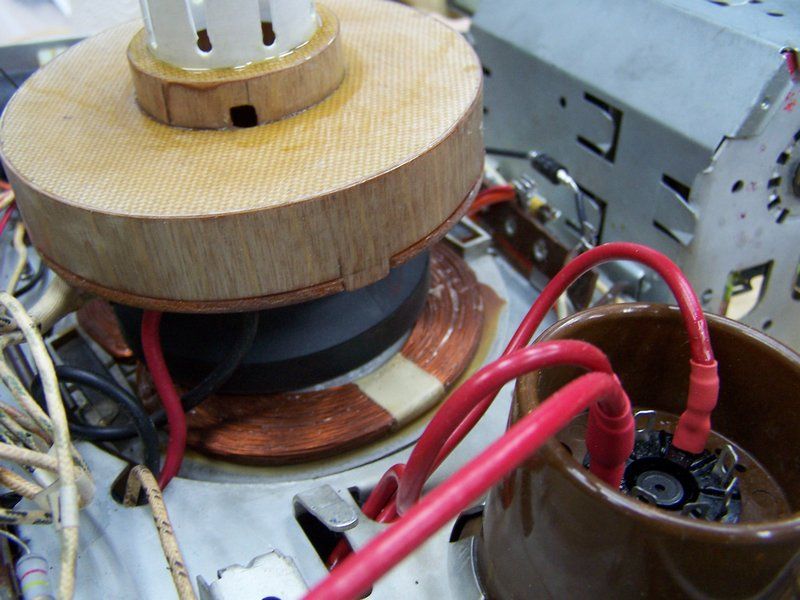
I've been working on the cabinet this weekend. Pictures to follow tomorrow. Here are a couple. The first one is of the HV cage. I coated the fly back with several heavy coats of Super Corona dope to seal the cracks and to keep the wax from breaking off.  Here's a picture of the 2A Slo-Blo fuse I added. 
|
|
#93
07-12-2017, 05:02 PM
|
|||
|
|||
|
The yoke cover is in sad shape. The back face is completely crumbled. The centering ring and holder is separated.
  My buddy thinks he might have a good one for me but it won't be till the weekend for him to see. So I decided to make one. I was going to use the plastic approach like Bob Andersen did but couldn't find the right plastic. So I made one with the materials I had at hand. I had some 1/16 thick phenolic, some 1/64 plywood, some 1/32 plywood, and some PVC sprinkler pipe that I use when re-stuffing E-caps. I first drew it out using my CAD program. Then printed out the parts and tacked them onto the phenolic. I cut them out and filed and sanded them to shape. Once the rings were made I decided that 2 layers of 1/64 plywood would work as the "rims" with the butt joints 180 degrees apart. For the "clamping" part I used some PVC sprinkler pipe but the O.D. was just a little too big and it has a wall thickness of 1/16 inch. I thought that that might be too thick and it needed to be 1/32 wall thickness. I rotated a 1 inch long piece up against my disc sander and sanded down the pipe to 1/32 wall. It is easier than you think. Just have to keep checking your progress. I then used some super glue to glue on the large rim, then the other rim on top of the first. I soaked the super glue down the joint between the two pieces. I then sanded it down to the correct height and drew a 1/8 line along the edge for the tabs. The tabs are 3/8 wide 90 degrees apart. I used my Dremel with a 1/2 sanding drum to sand away that 1/8 inch between the tabs. A small hand file was used to get the corners of the tabs. I then used some 15 minute epoxy to form a fillet along the inside edge for strength. I did the same for the centering ring holder portion. I drilled 1/8 holes in the sprinkler pipe every 3/8 inch to from the fingers. I then used a #11 blade in my hobby knife to cut the slots. This was then epoxied in place. The wooden parts were given a soaking of super glue to seal them, a light sanding and then some primer. Again some light sanding and some gloss black will complete the assembly. The black is drying as I type.        
Last edited by Crist Rigott; 07-12-2017 at 05:07 PM.
|
|
#94
07-12-2017, 07:33 PM
|
||||
|
||||
|
Impressive work, Crist!
|
|
#95
07-12-2017, 08:22 PM
|
|||
|
|||
|
Quote:
|
| Audiokarma |
|
#96
07-12-2017, 08:24 PM
|
||||
|
||||
|
Very nice work. I'm just worried about that flyback. What are the three wires going to the second anode?
__________________
"Tubes are those little glass things that light up orange unless there is a short.. Then they light up all pretty colors..." Please join my forum. http://www.tuberadioforum.com/
|
|
#97
07-12-2017, 08:29 PM
|
|||
|
|||
|
Quote:
I'm not sure what 3 wires you are talking about. There's a red one, and black one which goes to the yoke, and I think there's a white one and I'm not sure where it goes. I have the cover on the HV cage.
|
|
#98
07-12-2017, 08:33 PM
|
||||
|
||||
|
Where does the black wire come from? If it's the yoke, very likely it goes to one of the taps on the flyback.
__________________
"Tubes are those little glass things that light up orange unless there is a short.. Then they light up all pretty colors..." Please join my forum. http://www.tuberadioforum.com/
|
|
#99
07-12-2017, 09:28 PM
|
|||
|
|||
|
Quote:
|
|
#100
07-13-2017, 12:32 PM
|
||||
|
||||
|
That fly looks great! This was a common Philco issue and one of my sets like this has its fly covered in clear silicone.
Also, the yoke cover reconstruction may be the first one done on this forum.I was considering trying to "print" using a 3D printer but not sure the polymer would stand the heat in this application. An .stl file also needed to be created, which stopped the project.
__________________
"When resistors increase in value, they're worthless" -Dave G
|
| Audiokarma |
|
#102
07-13-2017, 08:50 PM
|
|||
|
|||
|
Quote:
|
|
#103
07-13-2017, 08:55 PM
|
|||
|
|||
|
The paint is dry and then I installed the centering ring assembly. There are 2 small tabs on the brass parts that fit into the square cutouts. The cutouts are positioned so that the tabs are inserted into those slots they maintain some pressure on the centering rings. While this worked I installed an "O" ring to apply some more pressure. Worked well.
  I then installed the chassis into the cabinet and installed the front panel. Next up is to do an alignment.  
|
|
#104
07-13-2017, 08:57 PM
|
|||
|
|||
|
BTW, can anybody indentify the equipment in the shop as shown in the last picture of ALF?
|
|
#105
07-13-2017, 10:21 PM
|
||||
|
||||
|
Quote:
__________________

|
| Audiokarma |
 |
|
|


 Linear Mode

