Videokarma.org

Go Back   Videokarma.org TV - Video - Vintage Television & Radio Forums > Early B&W and Projection TV

We appreciate your help

in keeping this site going.
Reply
 
Thread Tools Display Modes
  #1  
Old 07-02-2022, 09:54 AM
Chris K Chris K is offline
VideoKarma Member
 
Join Date: Jun 2022
Posts: 664
Thanks... gettin there. Thanks to VK I've gone from a blank screen to this in less than a week! The original capacitor carnage is below.
Attached Images
File Type: jpg IMG_20220702_105155485.jpg (72.2 KB, 31 views)
Reply With Quote
  #2  
Old 07-03-2022, 11:36 PM
Phil Nelson's Avatar
Phil Nelson Phil Nelson is offline
VideoKarma Member
 
Join Date: Jan 2006
Posts: 4,030
Quote:
Originally Posted by Chris K View Post
Picture is getting better!
Excellent -- looks like you are in the home stretch.

I don't know if you ran across it, but my website has an article describing how I restored my 721TCS (same chassis in a console cabinet):

https://antiqueradio.org/RCA721TCSTelevision.htm

These sets can definitely make a fine picture.

Enjoy!

Phil Nelson
Phil's Old Radios
https://antiqueradio.org/index.html
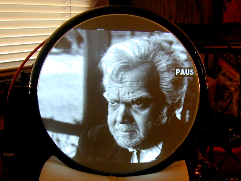
Reply With Quote
  #3  
Old 07-05-2022, 05:48 AM
Chris K Chris K is offline
VideoKarma Member
 
Join Date: Jun 2022
Posts: 664
Absolutely Phil...your site was the first one I saw when investigating and researching this restoration. I love the picture grab from GWTW! Good Ole Daddy O'Hara half nuts from Lee's surrender at Appomattox.

My next task is to start running down a couple of remaining issues. First, it looks like I'm only getting around 4Kv on the HV anode. It's enough to give it a decent picture since it's only an 8.5Kv CRT but I'm kinda stuck as to where I go from here. BTW, the HV measurement was done on the anode while it was disconnected from the CRT. IDK if that makes any difference. The second issue is sound. There isn't any. The speaker tests fine and the AOT ohms out perfectly. I am getting some funky voltages on the audio output tube. I can post on them more specifically this evening.

Thanks for chiming in Phil. Best
Chris
Reply With Quote
  #4  
Old 07-05-2022, 06:16 AM
Chris K Chris K is offline
VideoKarma Member
 
Join Date: Jun 2022
Posts: 664
Quote:
Originally Posted by Electronic M View Post
Your tuner should have detents. IIRC around then RCA was using a ball bearing and spring to make a detent and if the ball falls out you loose detent.

A DTV converter box alone won't work. You can use an HDMI to ATSC modulator if you want (it's expensive, but has it's advantages). In this video I discuss doing just that in my set up. https://m.youtube.com/watch?v=hKjt3x4WtWU

An HDMI* or VGA to composite video converter and RF modulator is cheaper and will also work. * DVI, Display Port, and HDMI use the same basic electrical interface so you can buy a cheap dumb DVI to HDMI or display port to HDMI cable if your computer doesn't have HDMI output.
Hi Tom...would something like this work? I do have an HDMI output port from my computer.

https://www.amazon.com/HDMI-Converte.../dp/B07W58PNPP
Reply With Quote
  #5  
Old 07-05-2022, 08:42 AM
Notimetolooz's Avatar
Notimetolooz Notimetolooz is offline
VideoKarma Member
 
Join Date: Mar 2014
Location: Dallas, TX
Posts: 548
You probably didn't need to replace the rectangular mica capacitors. Electrolytic and paper dielectric are the ones that are important. You can mess up the alignment if some mica or ceramic caps are replaced.

Some computers (probably older) have an analog video output.

The analog video output would have to go through a RF (NTSC) modulator to put it onto a TV channel that you can feed into the antenna terminals.

How did you measure the HV? It could be that your measurement method could be loading the HV more than the CRT.
Reply With Quote
Audiokarma
  #6  
Old 07-05-2022, 09:18 AM
Yamamaya42's Avatar
Yamamaya42 Yamamaya42 is offline
VideoKarma Member
 
Join Date: Nov 2018
Location: Round Rock TX
Posts: 2,624
Quote:
Originally Posted by Notimetolooz View Post
You probably didn't need to replace the rectangular mica capacitors. Electrolytic and paper dielectric are the ones that are important. You can mess up the alignment if some mica or ceramic caps are replaced.

Some computers (probably older) have an analog video output.

The analog video output would have to go through a RF (NTSC) modulator to put it onto a TV channel that you can feed into the antenna terminals.

How did you measure the HV? It could be that your measurement method could be loading the HV more than the CRT.
I was thinking the same thing, the mica domino capacitors did not need to be changed, however the one on the far left may be a paper “wolf in sheep's clothing” type domino.
There were 2 in my FADA set that I thought was mica, until one of them decided to let me know that they were paper by exploding and making a big mess!
__________________
=^-^=
Yasashii yoru ni hitori utau uta. Asu wa kimi to utaou. Yume no tsubasa ni notte.
いとおしい人のために
Reply With Quote
  #7  
Old 07-05-2022, 09:49 AM
Chris K Chris K is offline
VideoKarma Member
 
Join Date: Jun 2022
Posts: 664
Quote:
Originally Posted by Notimetolooz View Post
You probably didn't need to replace the rectangular mica capacitors. Electrolytic and paper dielectric are the ones that are important. You can mess up the alignment if some mica or ceramic caps are replaced.

Some computers (probably older) have an analog video output.

The analog video output would have to go through a RF (NTSC) modulator to put it onto a TV channel that you can feed into the antenna terminals.

How did you measure the HV? It could be that your measurement method could be loading the HV more than the CRT.
I measured the HV with a B&K 0-40kv range test probe with the kilovolt meter on the probe, grounded to the chassis...actually I tried grounding to the chassis and the HV cage and the readings were the same.

Yes, the dark dominos are paper but, I changed the micas for 2 reasons...they were a bit out of spec and Phil, who graciously chimed in above, changed the micas in his restoration. The micas I replaced were in the horizontal trimmer area for frequency, output and lock. Is it possible to change the HV output by moving the horizontal output adjustment?
Reply With Quote
  #8  
Old 07-05-2022, 10:01 AM
Chris K Chris K is offline
VideoKarma Member
 
Join Date: Jun 2022
Posts: 664
Quote:
Originally Posted by Notimetolooz View Post
You probably didn't need to replace the rectangular mica capacitors. Electrolytic and paper dielectric are the ones that are important. You can mess up the alignment if some mica or ceramic caps are replaced.

Some computers (probably older) have an analog video output.

The analog video output would have to go through a RF (NTSC) modulator to put it onto a TV channel that you can feed into the antenna terminals.

How did you measure the HV? It could be that your measurement method could be loading the HV more than the CRT.
Here is the B&K
Attached Images
File Type: jpg HV B&K.jpg (52.6 KB, 11 views)
Reply With Quote
  #9  
Old 07-05-2022, 03:13 PM
bandersen's Avatar
bandersen bandersen is offline
RCA 741PCS
 
Join Date: Mar 2009
Location: Chicago, IL
Posts: 8,106
He knows. He was posing it as an example of what happens when you don't have a filter cap.

The outer coating of the CRT should be ground. It allows the CRT itself to act as a filter capacitor for the high voltage.
__________________
Here are my Vintage Radio & TV YouTube Channel and Photo Gallery
Reply With Quote
  #10  
Old 07-06-2022, 06:00 AM
Chris K Chris K is offline
VideoKarma Member
 
Join Date: Jun 2022
Posts: 664
Quote:
Originally Posted by bandersen View Post
He knows. He was posing it as an example of what happens when you don't have a filter cap.

The outer coating of the CRT should be ground. It allows the CRT itself to act as a filter capacitor for the high voltage.
Hey there...thanks so much for chiming in. I've been watching your restore on this unit over and over. Yes, the graphite coating on the CRT contacts 2 wire loops on the yoke frame when the CRT is pushed all the way in. I'm not going to obsess over the HV reading. The picture is OK at this point and I'm going to turn my attention to getting some sound.

I've been working backwards from the speaker in the troubleshooting. Speaker pops and moves on contact with a 9v battery. AOTrans ohms out ok and there's continuity all the way back to the AOTube sockets but that's where it gets dicey. Filament voltages are OK and the tube is new but there's all sorts of out of spec voltages on the other pins. I was going to get a read on them last night and post but I never got off the couch and YouTube all night!!!
Reply With Quote
Audiokarma
  #11  
Old 07-06-2022, 01:08 PM
bandersen's Avatar
bandersen bandersen is offline
RCA 741PCS
 
Join Date: Mar 2009
Location: Chicago, IL
Posts: 8,106
It is not a hot chassis. I believe the original cord would by vinyl not rubber.

BTW less expensive and more readily available Slip Plate graphite coating works well on CRTs.
__________________
Here are my Vintage Radio & TV YouTube Channel and Photo Gallery
Reply With Quote
  #12  
Old 07-06-2022, 01:15 PM
Chris K Chris K is offline
VideoKarma Member
 
Join Date: Jun 2022
Posts: 664
[QUOTE=bandersen;3242720]It is not a hot chassis. I believe the original cord would by vinyl not rubber.

BTW less expensive and more readily available Slip Plate graphite coating works well on CRTs.[/QUOTE

Great...one less shock hazard! I'll google SP and check price and availability. I've got a Zenith and a Philco Seventeener where the dag is flaking off in big chunks!
Reply With Quote
  #13  
Old 07-06-2022, 05:48 PM
Chris K Chris K is offline
VideoKarma Member
 
Join Date: Jun 2022
Posts: 664
Nice loud tone on the FM radio BTW from the Knight
Reply With Quote
  #14  
Old 07-06-2022, 06:27 PM
Chris K Chris K is offline
VideoKarma Member
 
Join Date: Jun 2022
Posts: 664
...and here's the schematic...half of it anyway
Attached Images
File Type: jpg 721 Schematic.jpg (114.8 KB, 11 views)
Reply With Quote
  #15  
Old 07-06-2022, 06:42 PM
Yamamaya42's Avatar
Yamamaya42 Yamamaya42 is offline
VideoKarma Member
 
Join Date: Nov 2018
Location: Round Rock TX
Posts: 2,624
I'm using this!
https://www.earlytelevision.org/pdf/..._rider_tv1.pdf
__________________
=^-^=
Yasashii yoru ni hitori utau uta. Asu wa kimi to utaou. Yume no tsubasa ni notte.
いとおしい人のために
Reply With Quote
Audiokarma
Reply


Posting Rules
You may not post new threads
You may not post replies
You may not post attachments
You may not edit your posts

BB code is On
Smilies are On
[IMG] code is On
HTML code is Off

Forum Jump


All times are GMT -5. The time now is 04:37 PM.


Powered by vBulletin® Version 3.8.4
Copyright ©2000 - 2024, Jelsoft Enterprises Ltd.
©Copyright 2012 VideoKarma.org, All rights reserved.